Check if the user code measures PCLK properly. If it doesn't, then the baud rate calculation will be wrong. Since one of the symptoms that has been seen is that the RX light on the FT232 doodad flickers, but no characters appear in putty, it is possible that the baud rate isn't what we think it is.
Consider also calculating the baud rate registers and stuffing them manually. If this works, then it's the PCLK stuff that is broken.
Thursday, March 31, 2016

Friday, March 11, 2016
The Secret to Success
- Pick something you like doing.
- Do it and do it and do it until you don't like doing it any more. This will always happen at some point.
- Keep doing it.
Tuesday, February 16, 2016
Cortex M4 FPU
For a while I was having trouble getting my part to print any FPU calculations. Finally it occurred to me that maybe the FPU has to be turned on, and that the ISP wasn't doing it since it didn't use it.
It turns out that you DO need to turn on the FPU:
In effect, the FPU is counted as coprocessor 10 and 11. Cortex-M doesn't fully support the concept of coprocessors, but it does in this context. We allow full unpriveleged access to coprocessors 10 and 11.
I don't know about waiting for the store to complete and resetting the pipeline. I just put some C++ code to do this long before the FPU is used, and let a bunch of other work instructions flush the pipeline.
It turns out that you DO need to turn on the FPU:
4.6.6 Enabling the FPU
The FPU is disabled from reset. You must enable it before you can use any floating-point instructions. Example 4-1shows an example code sequence for enabling the FPU in both privileged and user modes. The processor must be in privileged mode to read from and write to the CPACR.
Example 4-1 Enabling the FPU; CPACR is located at address 0xE000ED88
LDR.W R0, =0xE000ED88
; Read CPACR
LDR R1, [R0]
; Set bits 20-23 to enable CP10 and CP11 coprocessors
ORR R1, R1, #(0xF << 20)
; Write back the modified value to the CPACR
STR R1, [R0]; wait for store to complete
DSB
;reset pipeline now the FPU is enabled
ISB
In effect, the FPU is counted as coprocessor 10 and 11. Cortex-M doesn't fully support the concept of coprocessors, but it does in this context. We allow full unpriveleged access to coprocessors 10 and 11.
I don't know about waiting for the store to complete and resetting the pipeline. I just put some C++ code to do this long before the FPU is used, and let a bunch of other work instructions flush the pipeline.
Friday, February 12, 2016
Getting on board the LPC4078
A few things make the LPC4078 dramatically different from the LPC2148 that I am used to:
I'm not there yet.
I haven't gotten my code to run directly yet, so there is still a problem with my vector table. But, I can get my code to run with the help of the ISP, after some experimentation.
The ISP maps a total of 512 (0x200) bytes of memory as its vector table. This is room for 128 vectors, while the actual number of vectors it uses is only 7. I can tell because the reset vector points at what would be in slot 7. In any case, this code is mapped to address 0 at startup. When I was using the ISP to launch my code, I originally had only exactly enough memory reserved to hold my table, and my code started immediately after, at address 0xE4 as it happened. Well, that code was covered up by the bootstrap. After rearranging my program so that a full 512 bytes was allocated for the table, things worked much better.
Also, the ISP uses an autobaud feature when it sets up the serial port. You send a question mark, and it times the bits on that to set up thebaud rate registers. However, the ISP uses a feature I don't, and that is the fractional baud rate register. This is able to tune the baud rate at a relatively fine grain to between 1x and 2x the rate called for by the coarse baud rate registers. When the ISP is used to kick off my code, my code sets the coarse baud rate, but didn't touch the fractional baud rate register, which was left at about 1.5 . Therefore the part was programmed to talk at the wrong rate by 50%, out of tolerance for the serial port. The FT232 could tell that the part was talking, but couldn't understand any of it.
With those two things taken care of, I can now start my code with the ISP, from the very beginning of my code. Next step is to see what I am doing wrong such that my code doesn't start itself.
- This is a Cortex-M4, with a much different interrupt and reset vector table. Instead of a set of ldr pc,[pc,#24] instructions followed by addresses 24 bytes later, we have just a table of addresses. The first one is the value to put into the stack pointer upon reset (so there is no required stack setup code) and the second one is the value to put in PC on reset. Subsequent values include exception and interrupt handler addresses.
- As with the 2148, there is a bootstrap program. On reset, the bootstrap vector table is mapped to 0x00000000, rather than the more obvious solution of having the reset value of the vector table address register point at the bootstrap.
I'm not there yet.
I haven't gotten my code to run directly yet, so there is still a problem with my vector table. But, I can get my code to run with the help of the ISP, after some experimentation.
The ISP maps a total of 512 (0x200) bytes of memory as its vector table. This is room for 128 vectors, while the actual number of vectors it uses is only 7. I can tell because the reset vector points at what would be in slot 7. In any case, this code is mapped to address 0 at startup. When I was using the ISP to launch my code, I originally had only exactly enough memory reserved to hold my table, and my code started immediately after, at address 0xE4 as it happened. Well, that code was covered up by the bootstrap. After rearranging my program so that a full 512 bytes was allocated for the table, things worked much better.
Also, the ISP uses an autobaud feature when it sets up the serial port. You send a question mark, and it times the bits on that to set up thebaud rate registers. However, the ISP uses a feature I don't, and that is the fractional baud rate register. This is able to tune the baud rate at a relatively fine grain to between 1x and 2x the rate called for by the coarse baud rate registers. When the ISP is used to kick off my code, my code sets the coarse baud rate, but didn't touch the fractional baud rate register, which was left at about 1.5 . Therefore the part was programmed to talk at the wrong rate by 50%, out of tolerance for the serial port. The FT232 could tell that the part was talking, but couldn't understand any of it.
With those two things taken care of, I can now start my code with the ISP, from the very beginning of my code. Next step is to see what I am doing wrong such that my code doesn't start itself.
Tuesday, February 9, 2016
LPC4078 operational
I am continuing my project of doing robot stuff with a buddget of zero, plus the stuff on my bench. Well, the stuff on my bench includes a Loginator2368 purple board, and a box of LPC4078 Cortex-M4 microcontrollers. Those controllers happen to be pin-compatible with the LPC2368 the board was designed for. In this case that means that all the power pins have the same jobs and voltage levels (even if they have different names and perhaps different internal connections), all the special pins like reset are in the same place, and all the GPIO pins have the same numbers, and where the 2368 and 4078 have the same peripherals, they have compatible pin assignments.
One thing that the 4078 has that the 2148 doesn't is internal pullup resistors. I can take advantage of these to reduce the part count in several places.
Therefore I got out my soldering iron and finally attached the board and LPC4078. I was trying to figure out what was the minimum amount of components I could get away with, since I can't find my solder paste stencil for this board, and would have to manually solder everything. I decided to skip the power section, so no external battery or regulator. I skipped the USB section, the LEDs, and the voltage reference. I also skipped the crystal, since the part has an internal RC oscillator which is good enough for now. I even skipped all of the bypass caps.
The only part that it looked like I absolutely needed was the reset button, since my first read on the datasheet didn't show the reset pin as having a pullup. It turns out that it does, so, I didn't even need that. I did end up stealing a push button from another board and using it as a reset switch.
I did the normal SMD IC soldering thing. I carefully lined up the part on the board, then used a normal soldering iron and normal solder to glob all the pins on each side down, and to each other. I then used wick to clean up all the bridges. This naturally leaves the connections to the board intact. I then soldered on the reset button, more as a convenience than anything. (Next time, leave a reset terminal on the edge!) Also solder a shield 6-pin top-and-bottom connector onto the power and serial connections.
Then, hook it up to power. No smoke, the chip isn't hot, it passes the smoke test. But, I've seen this board not work before, with the LPC2368 that it was designed for. So, the real test is running the ISP.
?
Synchronized
Synchronized
OK
12000
OK
It works!!! I had to guess at the frequency it wants, since I don't have an oscillator attached at all. The internal RC oscillator runs at 12MHz, so I put that in.
Now to massively restructure the code. A Cortex-M4 is quite a different beast than an ARM7TDMI. It has an FPU and built-in VIC instead of the VIC as a peripheral. It also doesn't use 32-bit ARM instructions, but (mostly) 16-bit Thumb2 instructions. The 4078 is also a much different part than the 2148, with a different set of registers in different places. But, probably 90% of the code can be in common, if we carefully separate the code into the part which is different and the part which is common. That's the next big adventure. Throw one switch in the Makefile and compile for a 4078 instead of 2148.
One thing that the 4078 has that the 2148 doesn't is internal pullup resistors. I can take advantage of these to reduce the part count in several places.
Therefore I got out my soldering iron and finally attached the board and LPC4078. I was trying to figure out what was the minimum amount of components I could get away with, since I can't find my solder paste stencil for this board, and would have to manually solder everything. I decided to skip the power section, so no external battery or regulator. I skipped the USB section, the LEDs, and the voltage reference. I also skipped the crystal, since the part has an internal RC oscillator which is good enough for now. I even skipped all of the bypass caps.
The only part that it looked like I absolutely needed was the reset button, since my first read on the datasheet didn't show the reset pin as having a pullup. It turns out that it does, so, I didn't even need that. I did end up stealing a push button from another board and using it as a reset switch.
I did the normal SMD IC soldering thing. I carefully lined up the part on the board, then used a normal soldering iron and normal solder to glob all the pins on each side down, and to each other. I then used wick to clean up all the bridges. This naturally leaves the connections to the board intact. I then soldered on the reset button, more as a convenience than anything. (Next time, leave a reset terminal on the edge!) Also solder a shield 6-pin top-and-bottom connector onto the power and serial connections.
Then, hook it up to power. No smoke, the chip isn't hot, it passes the smoke test. But, I've seen this board not work before, with the LPC2368 that it was designed for. So, the real test is running the ISP.
?
Synchronized
Synchronized
OK
12000
OK
It works!!! I had to guess at the frequency it wants, since I don't have an oscillator attached at all. The internal RC oscillator runs at 12MHz, so I put that in.
Now to massively restructure the code. A Cortex-M4 is quite a different beast than an ARM7TDMI. It has an FPU and built-in VIC instead of the VIC as a peripheral. It also doesn't use 32-bit ARM instructions, but (mostly) 16-bit Thumb2 instructions. The 4078 is also a much different part than the 2148, with a different set of registers in different places. But, probably 90% of the code can be in common, if we carefully separate the code into the part which is different and the part which is common. That's the next big adventure. Throw one switch in the Makefile and compile for a 4078 instead of 2148.
Friday, January 8, 2016
Practical CRTP (or lack thereof)
I have recently performed an experiment where I took the Loginator code and removed all dynamic polymorphism in place of static polymorphism. The motivation was the fact that since the sensors were all hard-wired to the board, all references to them could be figured at compile-time, and static polymorphism plus the optimizer and inliner could make "better" code. I also had an irrational fear of the vtables being corrupted.
Having gone through this exercise, I think I can say that CRTP is not the right way to do static polymorphism. It works, but it is ugly and infectious. If a class uses an object which is defined with CRTP, that class itself must also be made to use CRTP. I don't know if the machine code produced is faster, but I do know that it is significantly larger.
The motivation for changing back is the hardware description block which I am adding to the Loginator code, in hopes of being able to unify the Logomatic, Loginator, Rocketometer, Rollercoasterometer, and Pocketometer. My idea is to be able to load the same binary image into any LPC2148 based hardware I have or make, and have the software read the hardware description block to see what hardware it is attached to. This is all done at runtime, so we need dynamic polymorphism again.
CRTP isn't all bad. It works fine for instance in the dump class, where you can use it to make specializations of dump which are resolved at compile time. The problem arises when you want to pass a CRTP object as a parameter. At that point, the reference or pointer to the object has to be CRTP also, which frequently causes the whole class to need to be CRTP.
The idea then is that the general-purpose drivers are built into the code, and constructed at runtime from the hardware description block.
Having gone through this exercise, I think I can say that CRTP is not the right way to do static polymorphism. It works, but it is ugly and infectious. If a class uses an object which is defined with CRTP, that class itself must also be made to use CRTP. I don't know if the machine code produced is faster, but I do know that it is significantly larger.
The motivation for changing back is the hardware description block which I am adding to the Loginator code, in hopes of being able to unify the Logomatic, Loginator, Rocketometer, Rollercoasterometer, and Pocketometer. My idea is to be able to load the same binary image into any LPC2148 based hardware I have or make, and have the software read the hardware description block to see what hardware it is attached to. This is all done at runtime, so we need dynamic polymorphism again.
CRTP isn't all bad. It works fine for instance in the dump class, where you can use it to make specializations of dump which are resolved at compile time. The problem arises when you want to pass a CRTP object as a parameter. At that point, the reference or pointer to the object has to be CRTP also, which frequently causes the whole class to need to be CRTP.
The idea then is that the general-purpose drivers are built into the code, and constructed at runtime from the hardware description block.
Tuesday, August 18, 2015
Magnum Torch
A magnum torch is an Extra Utilities block which prevents the spawning of hostile mobs within a certain space around it. How? Like this:
public static boolean isInRangeOfTorch(Entity entity)
{
for (int[] coord : magnumTorchRegistry) {
if ((coord[0] == entity.field_70170_p.field_73011_w.field_76574_g) &&
(entity.field_70170_p.func_72899_e(coord[1], coord[2], coord[3])) && ((entity.field_70170_p.func_147438_o(coord[1], coord[2], coord[3]) instanceof IAntiMobTorch)))
{
TileEntity tile = entity.field_70170_p.func_147438_o(coord[1], coord[2], coord[3]);
double dx = tile.field_145851_c + 0.5F - entity.field_70165_t;
double dy = tile.field_145848_d + 0.5F - entity.field_70163_u;
double dz = tile.field_145849_e + 0.5F - entity.field_70161_v;
if ((dx * dx + dz * dz) / ((IAntiMobTorch)tile).getHorizontalTorchRangeSquared() + dy * dy / ((IAntiMobTorch)tile).getVerticalTorchRangeSquared() <= 1.0D) {
return true;
}
}
}
return false;
}
This is a method which supports both the chandelier and magnum torch. Each of those has the getHorizontalTorchRangeSquared and getVerticalTorchRangeSquared methods. It doesn't matter how this method gets called, or what the obfuscated functions are. The important bit is that line which works with dx, dy, and dz. Those are obviously the distance from the torch to the entity in question (the mob trying to spawn). The formula looks like this:
\[\frac{\Delta x ^2+\Delta z^2}{h^2}+\frac{\Delta y^2}{v^2} \le 1 \]
Rearranging slightly, we see the formula for the surface and interior of an ellipsoid:
\[\frac{\Delta x ^2}{h^2}+\frac{\Delta z^2}{h^2}+\frac{\Delta y^2}{v^2} \le 1 \]
The semi-axes in the horizontal direction are both \(h\), while the semi-axis in the vertical direction is \(v\). Looking at the implementation of these blocks we see:
public float getHorizontalTorchRangeSquared()
{
if ((func_145838_q() instanceof BlockMagnumTorch)) {
return 16384.0F;
}
if ((func_145838_q() instanceof BlockChandelier)) {
return 256.0F;
}
return -1.0F;
}
public float getVerticalTorchRangeSquared()
{
if ((func_145838_q() instanceof BlockMagnumTorch)) {
return 1024.0F;
}
if ((func_145838_q() instanceof BlockChandelier)) {
return 256.0F;
}
return -1.0F;
}
So, the magnum torch clears a spheroid around itself with an equatorial radius of 128 meters and a polar radius of 32 meters. Similarly the chandelier clears a sphere around itself of radius 16 meters.
public static boolean isInRangeOfTorch(Entity entity)
{
for (int[] coord : magnumTorchRegistry) {
if ((coord[0] == entity.field_70170_p.field_73011_w.field_76574_g) &&
(entity.field_70170_p.func_72899_e(coord[1], coord[2], coord[3])) && ((entity.field_70170_p.func_147438_o(coord[1], coord[2], coord[3]) instanceof IAntiMobTorch)))
{
TileEntity tile = entity.field_70170_p.func_147438_o(coord[1], coord[2], coord[3]);
double dx = tile.field_145851_c + 0.5F - entity.field_70165_t;
double dy = tile.field_145848_d + 0.5F - entity.field_70163_u;
double dz = tile.field_145849_e + 0.5F - entity.field_70161_v;
if ((dx * dx + dz * dz) / ((IAntiMobTorch)tile).getHorizontalTorchRangeSquared() + dy * dy / ((IAntiMobTorch)tile).getVerticalTorchRangeSquared() <= 1.0D) {
return true;
}
}
}
return false;
}
This is a method which supports both the chandelier and magnum torch. Each of those has the getHorizontalTorchRangeSquared and getVerticalTorchRangeSquared methods. It doesn't matter how this method gets called, or what the obfuscated functions are. The important bit is that line which works with dx, dy, and dz. Those are obviously the distance from the torch to the entity in question (the mob trying to spawn). The formula looks like this:
\[\frac{\Delta x ^2+\Delta z^2}{h^2}+\frac{\Delta y^2}{v^2} \le 1 \]
Rearranging slightly, we see the formula for the surface and interior of an ellipsoid:
\[\frac{\Delta x ^2}{h^2}+\frac{\Delta z^2}{h^2}+\frac{\Delta y^2}{v^2} \le 1 \]
The semi-axes in the horizontal direction are both \(h\), while the semi-axis in the vertical direction is \(v\). Looking at the implementation of these blocks we see:
public float getHorizontalTorchRangeSquared()
{
if ((func_145838_q() instanceof BlockMagnumTorch)) {
return 16384.0F;
}
if ((func_145838_q() instanceof BlockChandelier)) {
return 256.0F;
}
return -1.0F;
}
public float getVerticalTorchRangeSquared()
{
if ((func_145838_q() instanceof BlockMagnumTorch)) {
return 1024.0F;
}
if ((func_145838_q() instanceof BlockChandelier)) {
return 256.0F;
}
return -1.0F;
}
So, the magnum torch clears a spheroid around itself with an equatorial radius of 128 meters and a polar radius of 32 meters. Similarly the chandelier clears a sphere around itself of radius 16 meters.
Monday, August 3, 2015
Gem of the Once-In-A-While: Ragel FSM generator
Yukari 3 ran a hand-built state machine to parse NMEA sentences coming from the GPS. It worked, but it was hard to maintain. I went looking for a tool that was a better solution. I was looking for something like a C++ template library that implements a state machine by abusing the template processor. What I found was Ragel.
This a nice, simple, clean program for generating finite state machines and weaving them into your programs. It does so in a way which I vastly prefer over Lex. It's main drawback is that since it is not a template library, it does require an external program to handle. Well, so do several other parts of my system. I use Perl without embarassment, so I will use Ragel similarly.
Ragel is structured very similarly to Yacc, in that it creates a program which executes user-chosen actions when a certain sentence form is encountered. However, it only handles part 1 languages, IE regular languages.
Ragel takes as input a source file written primarily in C/C++ (other languages are supported, but I don't use them) but which is marked with certain Ragel blocks. These blocks are used to define the machine and actions. The actions are written in the main language (C/C++ as I use it) and Ragel builds code which executes the state machine on an input stream and executes your actions as they come up.
It demonstrates a couple of interesting ideas, one of which is that you can just make up a new language and mix it into your existing source code.
Certain of the Ragel commands indicate where the state machine's tables should be written, where the state machine code should go, etc. Interfacing to the scanner is pretty simple.
A couple of examples below the fold:
This a nice, simple, clean program for generating finite state machines and weaving them into your programs. It does so in a way which I vastly prefer over Lex. It's main drawback is that since it is not a template library, it does require an external program to handle. Well, so do several other parts of my system. I use Perl without embarassment, so I will use Ragel similarly.
Ragel is structured very similarly to Yacc, in that it creates a program which executes user-chosen actions when a certain sentence form is encountered. However, it only handles part 1 languages, IE regular languages.
Ragel takes as input a source file written primarily in C/C++ (other languages are supported, but I don't use them) but which is marked with certain Ragel blocks. These blocks are used to define the machine and actions. The actions are written in the main language (C/C++ as I use it) and Ragel builds code which executes the state machine on an input stream and executes your actions as they come up.
It demonstrates a couple of interesting ideas, one of which is that you can just make up a new language and mix it into your existing source code.
Certain of the Ragel commands indicate where the state machine's tables should be written, where the state machine code should go, etc. Interfacing to the scanner is pretty simple.
A couple of examples below the fold:
Saturday, July 18, 2015
Sputnik Planum

Although, it looks like the polygonal cracks extend into (under) the rough material. You can see what looks like a whole plate of rough material surrounded by hills. Is the rough stuff on top of the smooth stuff?
Tuesday, July 14, 2015
#PlutoFlyby
As I type, there is a signal flashing across the solar system at the speed of light. It was transmitted by the New Horizons spacecraft, and while it is encoded in phase shift keying, circular polarization, ones and zeros, CCSDS packets, it carries a simple message. It's just a playback of engineering data. But, it carries the following important information, translated into English:

- I am still functioning properly and have survived flyby
- I have executed the observation sequence to this point, have made this many observations and recorded this much data
- I am going to shut up now and get back to recording data
Alternatively there is a lack of signal flashing across the solar system at the speed of dark, carrying the unfortunate message that New Horizons did not survive flyby, and this is the best picture of Pluto we will get for decades:

Saturday, June 27, 2015
Splitting a git repository
I keep all my hobby code in a big git repository. The problem is that it is too big. I have something like 28GB in it, of which the vast majority is data, by which I mean results of data-collection processes, such as photos, rocketometer data, etc. It also includes data acquired from other sources, such as spice kernels, shape models, image maps, etc. It is making everything slow.
So, the solution is to split the repository. We split it into code, data, and docs.
Now, how do we split a repository? One option is to use the data we have to build new repositories. We go through the existing one commit-by-commit, generate a diff, filter that diff so that only the right files go into the new repository, then make a new commit in the new repository, making sure to keep the commit message, user information, and timestamp.
That seems hard. Also, it seems like someone should have already done that. So, I did some research to see if anyone else has done this. Mostly I am looking for people who are permanently removing files from a repository. My idea is to make three copies of the existing repository, then remove the files that don't belong using the methods described on the Internet.
In the course of my research, I found a program called BFG. This program does a full remove of a large set of files, in a way that is much quicker than git filter-branch. In order to do this, we need to remove the files from the head of the repository, so we do things like this:
So, the solution is to split the repository. We split it into code, data, and docs.
Now, how do we split a repository? One option is to use the data we have to build new repositories. We go through the existing one commit-by-commit, generate a diff, filter that diff so that only the right files go into the new repository, then make a new commit in the new repository, making sure to keep the commit message, user information, and timestamp.
That seems hard. Also, it seems like someone should have already done that. So, I did some research to see if anyone else has done this. Mostly I am looking for people who are permanently removing files from a repository. My idea is to make three copies of the existing repository, then remove the files that don't belong using the methods described on the Internet.
In the course of my research, I found a program called BFG. This program does a full remove of a large set of files, in a way that is much quicker than git filter-branch. In order to do this, we need to remove the files from the head of the repository, so we do things like this:
- Make three copies of the original workspace with git clone --mirror . These are going to be the three new repositories, so call them code.git, data.git, and docs.git
- For each repository, check it out with git clone (no --mirror). This working copy is temporary. We will use the code repository as typical.
- Because of the way BFG works, we have to rename any folders which are called Data or Docs. BFG doesn't remove just /Data, but any folder called Data. As it turned out, there were some such files. They needed to be either renamed (to data and docs, note lower case), deleted, or moved.
- Remove the files from the working copy with git rm -r Data Docs .
- Move all the files and folders from code down one level, since the old code folder will be the new root: git mv code/* .; git rm code
- Commit and push the removal and move
- Now go back to the new mirrored repository code.git and run java -jar ~/bfg-1.12.3.jar --delete-folders Data and java -jar ~/bfg-1.12.3.jar --delete-folders Docs . This process runs very quickly.
- At this point, the repository is cleaned, you can't see any evidence of the files, but there are garbage objects which need to be removed to actually make the repository take less space. To do this, run git reflog expire --expire=now --all --verbose and git gc --prune=now --aggressive . Git garbage collection takes a long time and an immense amount of memory, more than the 8GiB my file server actually had. I had to run the gc over the network on my game rig, which has 32GiB.
- Now the repository is shrunk. We went from 28GB to 3GB for the code repository.
Friday, June 26, 2015
More on sensor lag
I have done further analysis of the practice runs, and also hooked up the PPS and recorded some data while fixed.
From the PPS data, the robot takes an average of 0.54s from the time that the PPS fires to the time that it finishes receiving and parsing the RMC sentence. This is true every 4 seconds out of 5, but every fifth second, the GPS sends a burst of GSA and GSV sentences, which apparently delays the RMC to an agonizing 0.96s.
During practice run 3, the log file YUKARI02.SDS was recorded when the robot ran into the barrel. During its run on the second leg, it reached a peak speed of 6.57kt, or over 354cm'/s. It had a sustained speed on the second leg of over 300cm'/s . This is around 3m/s.
So, the sentence is typically processed 0.54s or 150cm' delayed, but up to 0.96 or over 300cm' delayed. Plus, the fixes are uniformly randomly distributed relative to the actual time of waypoint passage, with the delay equally likely to be any time between 0 and 1 second. This is another 0-300cm' of delay, meaning that the robot will detect and react to the waypoint between 1.5m and 6m beyond. I pulled the waypoint back 6.6m when I did the short waypoint test.
From the PPS data, the robot takes an average of 0.54s from the time that the PPS fires to the time that it finishes receiving and parsing the RMC sentence. This is true every 4 seconds out of 5, but every fifth second, the GPS sends a burst of GSA and GSV sentences, which apparently delays the RMC to an agonizing 0.96s.
During practice run 3, the log file YUKARI02.SDS was recorded when the robot ran into the barrel. During its run on the second leg, it reached a peak speed of 6.57kt, or over 354cm'/s. It had a sustained speed on the second leg of over 300cm'/s . This is around 3m/s.
So, the sentence is typically processed 0.54s or 150cm' delayed, but up to 0.96 or over 300cm' delayed. Plus, the fixes are uniformly randomly distributed relative to the actual time of waypoint passage, with the delay equally likely to be any time between 0 and 1 second. This is another 0-300cm' of delay, meaning that the robot will detect and react to the waypoint between 1.5m and 6m beyond. I pulled the waypoint back 6.6m when I did the short waypoint test.
Tuesday, June 23, 2015
Yukari 4 and nowcasting
I have been convinced to do Yukari 4, by of all people, my lovely wife Kellie. I have a theory about what is wrong, and how to fix it with one wire and a software change.
Hey mom! I'm on the Internet!
I just noticed this picture on the Sparkfun AVC2015 site:
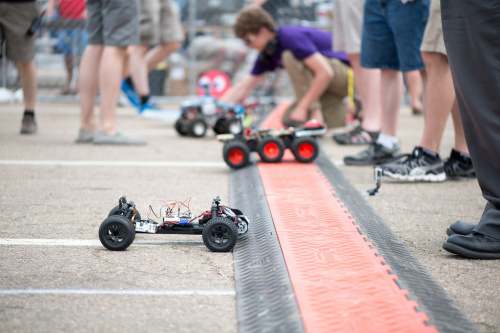
That's from AVC 2014, and that is Yukari II, breadboard and everything. Those are my toes on the right.
That's from AVC 2014, and that is Yukari II, breadboard and everything. Those are my toes on the right.
Saturday, June 20, 2015
Friday, June 19, 2015
Multipath
This thing might actually work. This morning the biggest problem I was having with it was the fact that the GPS was going crazy. I think it is multipath, and I think putting a big plane of copper below the antenna will work.
In the mean time, I have calibrated all the gyro axes, which needed a 15% scaling in order to read accurately. I trust the gyro compass far more than the GPS at this point, so I will tune the configuration parameters such that the GPS heading is ignored.
In the mean time, I have calibrated all the gyro axes, which needed a 15% scaling in order to read accurately. I trust the gyro compass far more than the GPS at this point, so I will tune the configuration parameters such that the GPS heading is ignored.
Wednesday, June 17, 2015
Operations Manual
The instructuions for the robot in its current state, which might actually work.
- The robot has two batteries, one for running the motors and one for running the controller. Make sure that both are charged. Use the motor battery charger to charge the motor battery. The battery may get hot during a charge, so its instructions say to charge it outside the vehicle. The controller may be charged either with the 5V/3.3V FTDI cable plugged into its jack, or with a USB MiniB plugged into the jack on the Loginator. Only do one of these, and don't try to charge with a 3.3V FTDI module.
- Make sure that the SD cards are in place. The Loginator card is the 16GB red/gray Sandisk card. It is a good idea to format it (backing up old data first, of course). Make sure that it has the proper CONFIG.TXT for the course. 'make format' will do both of these things. The camera card can be formatted using the menu of the camera.
- Set the switches as follows: SW1 (GPS TX->Loginator RX) is ON, SW2 (FTDI TX->Loginator RX) is OFF, SW3 (Boostrap mode) is ON.
- Make sure the GPS is in lock. You should see the red PPS light on the GPS interface blink once per second.
- Turn on the Loginator. You will see the light blink green or cyan, as the GPS and bootloader try and fail to talk to each other.
- Switch SW3 to OFF. This will boot the robot into the main firmware the next time that the controller is reset
- Turn on the motor power by sliding the switch forward. The green light on the ESC should blink but then stay off. If the steering is off-center, manually turn the wheels to center.
- Take the robot to the starting line. Approach the line from behind, and walk for several seconds in the direction the robot needs to go for the first leg. This sets the GPS heading appropriately.
- Set the robot on the line.
- Turn on the camera and start recording.
- At the starting signal, push the RESET button. This will boot the robot and it will take off within 2-4 seconds.
- When the robot comes to a halt, either due to finishing or to hitting an obstacle, turn the motor power off by sliding the switch backwards.
- Turn off the Loginator.
- Stop recording on the camera and turn it off.
- Remove the card, plug it into a computer, and copy the data from the card on to the host computer
- Use extractPacket and a spreadsheet to analyze the data. Use the NMEA files produced to drop into Google Earth for map visualization.
- Pull the MicroSD card from the camera and copy the results to the host.
The intended startup is slightly different:
- Make sure both batteries are charged as above.
- Make sure the SD cards are in place as above.
- Set the switches to SW1 ON, SW2 OFF, SW3 OFF (changed from above). We will bring the robot up into the main firmware, because it won't go until we push a button.
- Make sure the GPS is in lock as above.
- Turn on the Loginator as above. The red light for the LED should come on also, which means that the light will blink red/white. This is not an error condition - Those are indicated by a red or blue light blinking out a blink code at one second on, one second off. The robot is now recording GPS and inertial measurements, and actively sending zero throttle and steering commands.
- SW3 will already be off.
- Turn the motor on as above. It should center the steering automatically, and the drive wheels should not spin. The green light on the ESC should be steady on.
- Take the robot to the starting line by any route. The robot will no longer use GPS heading to initialize
- Set the robot so that it is pointed as accurately as possible towards the first waypoint. The robot assumes that its initial heading is towards the first waypoint, and uses that as its initial reference.
- Turn on the camera and start recording as above. Do this at least 5 seconds before the start of the race. Any jiggling is in principle remembered forever and incorporated int Average G, but in practice is more than 99% forgotten after 2.5 seconds.
- At the starting signal, push the STOP button on the Loginator or the green button. Do this quickly, since if the robot is jiggling before half a second before you push the button, the robot will incorporate that jiggling into its average G. We don't want that.
- When the robot stops, turn the motor off as above.
- Turn off the Loginator as above.
- Stop camera recording as above.
- Read the log as above.
- Use the analysis tools as above.
- Copy the camera video as above.
To burn a new program into the robot
- Set SW1 to OFF and SW2 to ON. Don't let both SW1 and SW2 be on at the same time.
- Set SW3 to ON.
- Plug in the FTDI cord to its jack, paying attention to the colors. The black wire is closest to the corner. Make sure there is no USB cord plugged into the Loginator USB jack.
- Reset the robot by pushing RESET on the Loginator. The robot should come up in bootloader mode.
- Use 'make program' to program the robot.
Tuesday, June 16, 2015
Heading Reference
The hardest thing is getting an accurate heading reference. There are at least 4 possible sources:
- Magnetic compass - We are carrying one, but it is close to the motor. I'll have to check some of the data to see if the motors influence it a lot.
- Gyroscope - Subject to random walk drift and needs an accurate starting heading
- GPS heading - The GPS calculates a heading itself and reports it in RMC
- GPS delta-position - Use trigonometry and the position 1 second ago
- We initialize the gyro using "Average-G". This is the average of the last 50 gyro readings on each axis. This average is subtracted from the in-motion readings to produce a zero-biased rotation rate
- We use the first RMC sentence to get our initial heading
- Once in motion, we use the gyro as the primary heading reference. We set up an inertial frame parallel to the initial orientation of the robot, and an initial identity quaternion. We use normal quaternion integration to integrate the gyro readings and get a new gyro-based orientation. We use that orientation to transform the vector pointing forward (the nose vector) from the body to the reference frame. The gyro heading is then the angle between the initial nose vector (same as the body nose vector) and the current nose vector. We use the initial heading to calculate the offset between the gyro heading and true north, and add this offset to the gyro heading to get the instantaneous heading relative to true north
- Whenever a large maneuver is executed, IE a large yaw rate is sensed, a countdown is set to 400 readings (4 seconds). When this countdown expires, we use method 4 to get the heading if the speed of the vehicle is high enough. We use this heading to calculate a new heading offset.
- We know the initial heading from the first two waypoints. Provided the robot is accurately aimed toward the waypoint, it will be plenty good enough.
- We are going to add a green button. Before the button is pushed, the robot will continually be recording the gyro readings, but will remember the last 50. Each reading, we will pop one reading out of the queue, and average it with the running total. The weighting will be 1 point for the new reading and 49 for the old average. In effect this takes the average of all the measurements from robot reset, but each old measurement has an exponentially decaying weight. We include some code to wait for 49 measurements before using a weighting of 49. We remember 50 measurements because the very act of pushing the green button will cause the robot to shake and will ruin the current measurements.
Monday, June 15, 2015
(Real life) Failure
Time to test the robot in the real world. Because it is faster than I am, and because I don't trust it, and because I am testing it on the open road, I am testing it by carrying it, walking with it, and turning myself and the robot as its steering wheels turn. Here is the first result: The green line is the intended course, and the blue track is the measured track (it actually started almost exactly on the start of the green line, and never travelled towards the west).

Notice that it didn't turn. Analysis of the guidance packets suggests that the robot was only going at one tenth the rate we expected. As a consequence, when it reached the waypoint in reality, it only thought it had reached one tenth of the way to the waypoint. What happened? It seems to be a problem related to parsing the GPS data. The simulator gave out data with 7 digits after the decimal place, while the real GPS uses 4. In both cases, the intent was to force the length to 5 digits. It turned out that the code was forcing the part after the decimal point to 4 digits, if the number needed to be stretched, which is the case for real data and not for simulated data. The effect was that the fractional minute part was only 1/10 of what we expected. As it happens, the test course does not cross a whole-minute grid line, so the gigantic leap when it thinks it is going from 11.09999 to 12.00000 doesn't happen. The robot only thinks it is going 1/10 as far as it really is going.
Furthermore, this test inspired a new simulator/reality hybrid, called playback. The playback program is quite similar in structure to the simhost program from before. The difference is that it reads a recording from a real robot run rather than simulating from scratch. Whenever a gyro packet is encountered in the recording, a simulated gyro reading with the same DN and timestamp is created. Whenever an NMEA packet is found, this is stuffed into the virtual GPS serial port. In both cases the simulated timestamp is set to the time indicated in the packet.
I was able to put the actual robot code under the microscope with gdb and the playback seen above, and by stepping it there, found the problem with the NMEA parsing. I am not able to use playback to completely test the fix, but I can check if the robot tried to turn at the waypoint.
Results:
The simulator was adjusted to only give 4 digits after the decimal and was re-run against the actual AVC course, to see that this still works, and it does.
 The donuts are "victory donuts" done after the robot crosses the finish line. Victory donuts are a bug, but they are after the robot crosses the finish line.
The playback also changes waypoints at about the right time, if I actually have it using the right course. Too many times I ran the playback with the AVC course rather than the local test course.

Notice that it didn't turn. Analysis of the guidance packets suggests that the robot was only going at one tenth the rate we expected. As a consequence, when it reached the waypoint in reality, it only thought it had reached one tenth of the way to the waypoint. What happened? It seems to be a problem related to parsing the GPS data. The simulator gave out data with 7 digits after the decimal place, while the real GPS uses 4. In both cases, the intent was to force the length to 5 digits. It turned out that the code was forcing the part after the decimal point to 4 digits, if the number needed to be stretched, which is the case for real data and not for simulated data. The effect was that the fractional minute part was only 1/10 of what we expected. As it happens, the test course does not cross a whole-minute grid line, so the gigantic leap when it thinks it is going from 11.09999 to 12.00000 doesn't happen. The robot only thinks it is going 1/10 as far as it really is going.
Furthermore, this test inspired a new simulator/reality hybrid, called playback. The playback program is quite similar in structure to the simhost program from before. The difference is that it reads a recording from a real robot run rather than simulating from scratch. Whenever a gyro packet is encountered in the recording, a simulated gyro reading with the same DN and timestamp is created. Whenever an NMEA packet is found, this is stuffed into the virtual GPS serial port. In both cases the simulated timestamp is set to the time indicated in the packet.
I was able to put the actual robot code under the microscope with gdb and the playback seen above, and by stepping it there, found the problem with the NMEA parsing. I am not able to use playback to completely test the fix, but I can check if the robot tried to turn at the waypoint.
Results:
The simulator was adjusted to only give 4 digits after the decimal and was re-run against the actual AVC course, to see that this still works, and it does.

The playback also changes waypoints at about the right time, if I actually have it using the right course. Too many times I ran the playback with the AVC course rather than the local test course.
Friday, June 12, 2015
(Simulated) Success!
If my robot does this at the competition, it will represent full mission success: scoring at least one point.
 The left is a spreadsheet plot of the simulated position, and the right is the simulated GPS data dropped into Google Earth.
I had gone into this thinking that the software was good and the hardware flaked out last year. I made a bunch of changes to the software, and it got worse before it got better, but I suspect there were enough bugs in the old code that it wouldn't have worked even if the hardware had worked. Last year, it did try to turn, though.
This proves the value of a good simulation. I have simulated the race more than 100 times, including times when the robot just drove around in circles. The above run was the first which actually successfully sought a waypoint. More about the simulation below the fold.

I had gone into this thinking that the software was good and the hardware flaked out last year. I made a bunch of changes to the software, and it got worse before it got better, but I suspect there were enough bugs in the old code that it wouldn't have worked even if the hardware had worked. Last year, it did try to turn, though.
This proves the value of a good simulation. I have simulated the race more than 100 times, including times when the robot just drove around in circles. The above run was the first which actually successfully sought a waypoint. More about the simulation below the fold.
Subscribe to:
Posts (Atom)