Howbout the anti-gravity evil launchinator. There, I changed the name, that makes it mine.
--Dr. Heinz Doofenshmirtz
So I took advantage of the Open Hardware nature of the Sparkfun Logomatic, made a few tweaks and ended up with the Loginator. This board is 100% backwards pin compatible with the Logomatic and 99% firmware compatible. It has a number of cool features and annoyance fixes, described below.
New features and improvements:
Boot button - This shorts the USB detect line, causing the USB bootloader to think that the USB has become disconnected. This causes the bootloader to check for a new main firmware, install it if necessary, then run it. Basically it prevents having to unplug and replug the USB when you are debugging things and want to rapidly start the main firmware. Plus, this way you don't need a battery to maintain power across the USB unplug, so you can run the main firmware without a battery.
RGB LED - This replaces the STAT lights on the Logomatic. The red and green lights are connected to different pins on the microcontroller, so the Sparkfun firmware will have to be slightly modified to accommodate. The blue light is available also. Formerly the lights were attached to the same pins needed for I2C. Now they are attached to PWM pins. Unfortunately, two of these PWM pins are connected to TX and RX for UART0. There is a solder bridge next to the LED. When shorted, the lights work, and when not, the lights are out and don't interfere with the UART. If you leave them on and use UART0, then the lights will blink as the port transmits and receives.
I2C ports - The LPC2148 has two hardware I2C ports. Unfortunately on the Logomatic, these pins are used for things like the STAT lights and STOP button. The Sparkfun firmware will have to be slightly modified to use the new stop button pin.
Current sensor - The Logomatic had a battery voltage sensor set up on an otherwise unused ADC channel. The Loginator includes this, but also a current sense resistor and amplifier on the input to the 3.3V regulator so you can see how much current the device is using. This current sensor uses a pin which was not connected on the Logomatic.
Improved power supply - The Logomatic could run on USB only, and could run on USB while simultaneously charging the battery, but only do to a quirk in the particular charging circuit used in the Logomatic 2.3.With no battery connected, the charging circuit powers the load only because it thinks that the rest of the Logomatic is a battery to be charged. I tried a couple of newer non-obsolete chargers and couldn't get them to work like this. The new circuit has a set of bypass diodes such that when the USB is plugged in, it explicitly powers the circuit and cuts the charger off from the rest of the circuit. On battery power, the diodes cut off the USB, and if both are plugged in, whichever is higer (always USB) wins. The charger only charges the battery then, not the rest of the circuit. The 3.3V regulator is also rated for 500mA to power external devices like GPS, LCD screens, etc. Since the power switch is only rated for 120mA, it now controls a fully-rated PMOSFET as the real power switch.
Voltage reference - The circuit has a 2.5V series absolute voltage reference attached to ADC pin 8. When connected, pin 8 must be an input on the Logomatic and an output on the board edge connector. If you don't want this, don't short the solder bridge next to the voltage reference. Then you are free to use pin 8 for anything.
11Dof port - This connects to a miniature board with 12 pins and a 3-axis accelerometer, 3-axis gyro, 3-axis magnetometer, and pressure/temperature sensor. The fast sensors, the acc and gyro, are connected to SPI1, while the slow sensors, baro and compass, are connected to I2C1. All the interrupt lines are broken out and connected to ADC pins which are repurposed as timer capture pins. More on this board in another post.
Round Corners - PCBs are hard, and the corners can be made arbitrarily sharp. These just don't feel good when you handle them. I got the idea to round off the corners from one of the photos on Laen's blog. These are 0.1" radius corners which happen to be centered on the mounting hole in each corner. I thought there might be a problem with such a thin bit of PCB there, but FR4 is one tough material.
Basically because the Open Hardware license is contagious, when I publish the design, it will be with the same terms that Sparkfun uses. The original Logomatic was designed by C. Taylor and N. Seidle at Sparkfun.com, and released with a Creative Commons attribution/share-alike 3.0 license.
The first thing to do of course is research. Maybe someone else, like the guys at JPL, have already published a trajectory. Poking through the files at JPL NAIF, I found a couple of kernels for MSL. One is labeled cruise, and one is labeled EDL. Now since there is no target set yet, these are obviously preliminary. I have read somewhere that this target is near the point that is easiest to retarget to any of the four candidate landing sites. These kernels are still interesting for just seeing what EDL is like. this is the comment section of the EDL kernel:
MSL Sample EDL Trajectory SPK File (Central Landing Site (0.0 N, 45.0 E)
==========================================================================
Created by Fernando Abilleira, MSL MD/NAV. Comments added by
Boris Semenov, NAIF/JPL on Tue Feb 23 16:34:24 PST 2010.
Objects in the Ephemeris
--------------------------------------------------------
This file contains sample MSL (NAIF ID -76) EDL trajectory, from
atmospheric entry interface point to landing, for Type 1B, open of
launch period (11/25/2011), optimal launch time, central landing
site (0.0 N, 45.0 E), landing time 06-AUG-2012 11:35:46.7 UTC.
THIS FILE SHOULD BE USED FOR TESTING PURPOSES ONLY.
Approximate Time Coverage
--------------------------------------------------------
This file coverage is:
COVERAGE BEGIN TIME (TDB) COVERAGE END TIME (TDB)
------------------------- ------------------------
2012 AUG 06 11:30:58.537 2012 AUG 06 11:36:52.837
If you have any questions regarding this data contact
Boris V. Semenov, NAIF/JPL,
(818)-354-8136,
Boris.Semenov@jpl.nasa.gov
This particular kernel is just a list of positions and velocities at specific times, typically 0.1s apart. The attached CSV is a dump of the kernel at those times, plus some bonus stuff you can read about in the file.
A couple of comments:
12 earth g's on entry! Phoenix peaked at 8.
It flies for a long time, starting to gain altitude at about 110s and not opening the chute until 250s
However, closer examination of this kernel yielded only disappointment.
Excursion funnels are part of an investigation into how well test subjects can solve problems when traveling through a churning funnel of liquid asbestos. Results so far have been highly informative: They cannot.
It doesn't look like this spice kernel can be used for the kind of aerodynamics model I am looking for. It just isn't of sufficient fidelity. For instance, the vehicle never has any significant side lift during the fight portion of the kernel, where we would expect the spacecraft to bank side-to-side. It just pitches further and further down, generating more and more lift, beyond any amount I have seen documented. Also, there is no orientation data associated with this kernel. I can fake it from the lift/drag ratio, but there is nothing authoritative.
However, there are several spacecraft events visible, including the jettison of the six entry balance masses, and I think the heat shield jettison. Data before about 40 seconds is unreliable because there is no significant air, and data after the parachute deploy at around ~250s is unreliable since my code doesn't take into account the new area of the parachute. The PDV separation at ~340s is visible, but the spice kernel ends at about 90m altitude above ground level and 2.5m/s verical speed.
So, what I am doing instead is using the Phoenix aerodynamic model. Apparently, entry capsule aerodynamics is so dominated by the heat shield that it hardly matters what the shape of the backshell is, and with proper scaling, the Phoenix coefficients can be applied to MSL directly. One of the interesting things is that the lift/drag ratio is an almost linear function of angle of attack and not a strong function of speed. So, by looking at the L/D from this plot, I can back out the angle of attack.
Further research reveals the no side-lift thing is intentional. See here .
Movie is in progress, but because of various glitches in the kernel, I'm not sure it will ever be worth publishing. What I would like to do is get the Orbiter model up and running, write a realistic entry guidance autopilot for it, and then collect data and make the movie with that.
Next friday, when all of us are relaxing after a fine day of turkey, the guys in Florida will be launching the Mars Science Laboratory.
Back when Phoenix was launched, the guys in Arizona put together a great video showing entry, descent, and landing with various events, all in real time. After the landing occured, the guys at JPL put together a reconstruction of the entry trajectory and orientation, and posted them as a pair of spice kernels. I was able to use this data and put together a cool video, showing the events in real time in proper scale. I had a model of the lander, its aeroshell and parachute, and the topography and map of the area around the landing site. The results came out pretty good:
So, of course I am going to do one for MSL. But, MSL hasn't flown yet and Absurd Accuracy is Our Obsession. So, I have to generate the trajectory and event data myself. I will document what I have done and what I am doing, building up hopefully to the release of this video on or before landing launch.
None about the rocketometer, as no one else has one (I don't even have one yet...) but about Logomatic Kwan. After publishing the thing in 2009 (has it really been that long?) I got letters from two people in two weeks.
First, I got one from a researcher at the University of Washington. His letter goes like this:
Chris,
First, thank you for publishing your firmware. I am just starting a project where I will be making a custom datalogger that will monitor various forces inside of a prosthetic socket as well as keep an inventory of socks the user is wearing. However, before I can start on the final product, I need data to get some funding. That is where the logomatic comes in, I am using that combined with a CAEN RFID board to collect the data I need. The CAEN communicates with the logomatic through the UART0 interface.
I am using the following command line to obtain the inventory data from the CAEN device: "H 1 0 8001000000005358002100000008000100130000000F00FB536F757263655F3000"
In the "LOK" file, I see where it prints out that line but the data is corrupted and there consistently an extra 16 bytes of data after. Here is a sample from the LOK file: "€ SX ! ûSource_0 4 8406 3540 2879"
So now you hopefully understand the background and I can ask my two questions. From your write-up, the data from the command line is printed in the log file, why is what is logged different from what is in the command file (e.g. 0x0 is converted to 0x20)? Second, is the extra 16 bytes at the end of the line received data?
I appreciate you getting back to me so quickly and look forward to hearing back from you.
This guy has a specific problem, he has told me what he has done, and is appropriately respectful and/or polite. After some conversation, I was able to solve his problem.
The converse is this:
Hello,
I have a logmatic v2 datalogger. I want to sample 2 pins. 1 pin for a pulse anemometer. The other pin voltage to sample a weathervane. And add the RTC value.
Can you help me?
Thanks.
This one for whatever reason rubbed me wrong. It almost struck me as asking for me to do his homework. There is no evidence that this guy has done anything on his own yet, or even that he has Logomatic Kwan. It is out of the blue, with no introduction or any idea how he found me (David S. didn't either, but the other factors outweighed that).
I probably can help him. The only reason I bring this up is that this might be an interesting problem. I actually deleted his message without answering it, just because it bugged me. But, I pulled it out and responded.
The first hit for "pulse anemometer" is here. This anemometer produces a ~50% square wave, one pulse for every 1m or so of wind travel. If the signal is 1Hz, then you end up with 1m/s of wind speed. Depending on if there is any bounce on the signal, it could be plugged into the PPS channel (SCK on the Logomatic) to get microsecond precision on the signal. If the signal is too bouncy, it would need to be sampled at a high rate, but that's what the Logomatic is for. It would produce vast amounts of data to be post-processed, but that's ok.
The letter is even less specific about the weathervane. I suppose it is analog, perhaps a sin/cos signal. The same manufacturers as above make a weathervane based on a 1000 ohm potentiometer, so voltage is proportional to angle from North. That is straightforward analog, and would be fine sampled at 10Hz.
If he runs the system in NMEA mode, he will get $PKWNL packets with the RTC he wants once every second.
So, I can help him, but he still needs to do quite a bit of work.
Or: You can't use an N-channel MOSFET as a high-side switch.
Update: NXP finally released an app note detailing what each part is for: AN11392 - Guidelines for full-speed USB on NXP's LPC microcontrollers (19 Feb 2014). Some of what I guessed below is right, while some is misleading, and it appears that the Sparkfun circuit doesn't even follow the specification. Notes above in my 2 Apr 2014 entry.
I am trying very hard to use all of my components within their specifications. One part that was having trouble was the power switch in the power supply.
First, a look at the power supply:
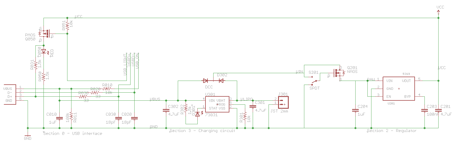
This is cool because I can finally explain each and every part in the USB circuit, something that I haven't seen online yet.
Let's take a closer look at the USB part:
All the parts are R0xx, C0xx, and so on because they are in section 0 of the board. The 10's digit specifies which main pin of the USB jack they are associated with, so for example R010 is associated with pin 1 (Vbus).
For Google, this is the USB to LPC2148 SOFTCONNECT INTERFACE
Parts list:
Quantity
Digikey Part
Value
Device
Part Numbers
2
490-1281-1-ND
18pF
CAP0402-CAP
C020, C030
1
490-3890-1-ND
1μF
CAP0402-CAP
C010
1
350-2029-1-ND
RED
LED0603
D050
1
455-2562-1-ND
USB_MICROB_JST
USB_MICROB_JST
J001
1
BSS84-FDICT-ND
PMOS
MOSFET-PCHANNELSMD
Q050
2
P10.0KLCT-ND
10k
RESISTOR0402-RES
R010, R051
1
P100KLCT-ND
100k
RESISTOR0402-RES
R011
2
P33.0LCT-ND
33
RESISTOR0402-RES
R020, R030
2
P1.50KLCT-ND
1.5k
RESISTOR0402-RES
R031, R050
A bit about the genealogy of this circuit. I originally got it from the Sparkfun Logomatic, which apparently was adapted from the Keil MCB2140 board, as explained by microbuilder.eu. All of these parts have a bunch of stuff not explained anywhere, and not mentioned on the LPC2148 datasheet, as seen below:
The Keil design combines the best features of these two suggestions, mostly using the top design but putting an LED in and implementing the switch with a PNP transistor.
I have made some further adaptations to reduce the pin count and eliminate the vile BJT transistor in favor of a good and virtuous FET. Someday I will explain why FETs are better, but they are. Use FETs when you can, and BJTs when you have to.
So, in part number order:
C010 is required by the USB spec. There must be between 1μF and 10μF between Vbus and Gnd as seen from upstream. If there is too little, the downstream device could be damaged by inductive flyback from the wire as it is disconnected. If there is too much, the inrush current to charge all that capacitance will be too high. The Sparkfun circuit had 0.1μF here, seemingly out of spec, but as it turns out, some of the capacitors downstream in the charger circuit are visible also. The Sparkfun circuit as a whole is within specs. This capacitor used to be higher until I noticed all the capacitance visible downstream.
R010 and R011 seem to be there to provide pull-up and pull-down if the USB plug is unplugged or shorted. If the plug is unplugged, there is a total of 110kΩ of pull-down, so that the pin has a defined non-floating value if it is input. If Vbus and Gnd are shorted, there is still 10kΩ of pull-down, and more importantly, if the controller pin is output and high, there is 10kΩ of current limit.
R020 and R030 are required by the USB spec. There must be between 28Ω and 44Ω of termination resistance. Accounting for the internals of the LPC2148, there must be a 33Ω resistor in series with each data line, as called out by the data sheet above.
C020 and C030, form the other half of a low-pass noise filter, when combined with R020 and R030. In this case, frequencies higher than 250MHz are filtered out. This prevents the channel from being used as a high-speed (480MHz) channel, but the LPC2148 isn't capable of this anyway.
R031 is required by the USB spec. When the downstream device (in this case the LPC2148) is ready to communicate, it ties in a pull-up resistor to one of D- (if low-speed) or D+ (if full-speed). Since the LPC2148 is a full-speed device (12MHz, up to 12Mb/s) it ties to D+.
Q050 is the SoftConnect switch. It is a P-channel FET used as a high-side switch, which takes a bit of explanation. In a P-channel device, the source is connected to high voltage, and the drain to ground. If the gate voltage is sufficiently lower than the source, the FET conducts. In this circuit, the source is connected to Vcc (3.3V) and the gate is connected to the USB_SOFTCONNECT (or USB_LIGHT) pin on the LPC2148. When that pin is low, the transistor turns on, and provides a low-resistance path to Vcc, in effect tying one end of R031 to Vcc, which tells the upstream host that this device is ready to communicate. When the pin is high, the transistor turns off, and that end of R031 is left floating.
D050 and R050 form an LED chain which lights whenever Q050 is on, or in other words, when SoftConnect is activated.
R051 is a pull-up resistor, so that when the LPC2148 is off or its SoftConnect pin is input (as it is just after reset) the transistor is off, since its gate is not floating.
Several of these parts seem to be optional, namely C020, C030, R010, R011, perhaps R051 if you aren't worried about the floating FET gate input, D050 and R050 if you don't want the light, and C010 if you have enough capacitance elsewhere. You absolutely need R020, R030, R031, and Q050.
On to the charging circuit. I use an MCP73831, programmed to charge at 100mA, since I am planning for a battery as small as 100mAh. I have added a diode network D302 since there is no clear description in the data sheet for the 73831 explaining what the circuit will do if there is USB power present but no battery. With this diode network, if USB is present but the battery is not, the USB line will directly power the load. If the battery is present but the USB is not, the battery will power the load. If both are present, the USB wins, and the charger just has to concern itself with the battery, not the load.
Finally, the regulator circuit, and why this entry is subtitled "You can't use an N-channel MOSFET as a high-side switch."
The regulator itself is a MIC5319, capable in principle of delivering 500mA. Not that this is needed with the IMUinator, but to provide for future design expansion. It is hooked up exactly as specified in its own datasheet. The interesting part is the switch between the regulator and battery. That switch is only rated for 100mA. So, I said, let's stick a FET in there. We pick a nice high-current, low resistance FET available in a SOT-23 package. Use the switch to turn on the FET, and the FET to turn on the resistor. And here is where I made my mistake. I chose an N-channel FET, because I wanted direct logic on the switch (switch on -> FET on) and I installed it on the high side so that the circuit would be grounded (except for a floating Vin) when the FET was off.
But, "You can't use an N-channel MOSFET as a high-side switch".The FET is more accurately a voltage-controlled resistor. When the gate-to-source voltage is high enough, the resistance drops, and effectively the FET is just a wire, with about 200mΩ of resistance. But, the voltage is gate-to-source, and the very fact of dropping resistance raises the source-to-ground voltage. The gate-to-ground voltage remains the same, but the gate-to-source voltage drops as the source-to-ground voltage rises. The switch turns itself off.
It's not quite this bad, but in a way it is worse. The device will find some stable in-between state, dependent on the voltage supplied and probably the load on the regulator output. This in-between state will not be high enough to actually do anything, but high enough to draw some power, and dissipate it right in the FET. With the USB plugged in, the input was about 4.67V and I was getting about 3.07V out of a 3.3V regulator, showing that the FET had stabilized at less than 3.3V, when I was expecting near 4.67V. When the battery was used, the value was about 2.7V, not even enough to run the LPC2148.
So, the possible solutions are:
Use a P-channel FET. This is what I would do if I had caught the design flaw early enough. The circuit would be identical, just the opposite switch position would now be on. Unfortunately, P-channel FETs and N-channel FETs both have the same pin assignments, so the source on the P-channel is the same pin as the source on the N-channel. However, the P-channel FET needs to have its source connected to high voltage, not low, so the board design would have to change. Since I already waited almost three weeks for the board, I can't do this.
Remove the FET entirely. This way we just connect the gate terminal on the board to the source, and use the mechanical switch as the main switch. Perfect if I could just remove that FET already soldered on the board, or if I built a new one with no FET, but I don't have those parts.
Short the FET. Don't remove it, just put a wire over the FET from gate to source. This will guarantee the gate-to-source voltage is zero, and therefore that the FET is off all the time. In the mean time, the voltage applied to the gate is shorted past the source to the load.
Update 20 Oct 2011: Shorting the FET worked. As it turns out, the gate and source are the two pins on the same side of the SOT-23 package, so shorting them was a matter of installing a solder bridge. I now get 3.285V out of the power supply with the battery and no load, a 0.5% difference from nominal which is well within spec and very well might be in my voltmeter rather than the regulator.
It's pretty easy to comb the net for trash-talk and criticism of the CadSoft Eagle autorouter. Honestly it's not very good. It's less good than I am at routing, and I'm not that good.
But, if you lack patience like I do, the autorouter is the way to go. You can set it loose on a problem, go get a soda, read some blogs, come back, and have an acceptable if not beautiful board.
I have gathered a couple of useful hints which has helped the success of my autorouting attempts enormously:
Do a good job placing components. Consider the hardware subroutine advice below.
Set the routing grid to a very small number. If you are using inches, set it to 1 mil. I think the routing time goes up with the inverse square of the grid size, so half the grid size takes four times longer, but often the router can find solutions with a smaller grid that elude it with a larger grid.
Consider the shape of your board, and the general "grain" of the signals on it. On long, skinny boards like the Stick IMUinator, it may not be best to prefer horizontal and vertical. Most of your signals will want to go horizontal, forcing most of them to one side of the board. Consider doing the preferred directions diagonally. I learned this by watching the FreeRouting.net autorouter work on my design.
Delete (not just rip up) your ground plane polygons. The autorouter doesn't seem to handle polygons well at all, but if the polygon is not there and it treats ground just like any other signal, it can usually handle it well.
Be prepared to do a manual cleanup after the autorouter is done. Put back the ground planes, and rip up all the lines, but not the vias, in the ground signal. Sometimes, you will find it necessary to leave a wire which connects parts of the ground plane. This especially happens if your ground planes use thermals. Also just fix any general ugliness on the board. For instance, the autorouter loves to bring a signal out the side of a QFP pad (like on the controller in the IMUinator) and bring it as close as possible to another pin before turning. Fix these manually.
Check if the router has done anything monumentally stupid. For instance on the Stick IMUinator, the main crystal has four pads, two of which need to be grounded and two which are the crystal terminals. These are diagonally opposed, so that the orientation of the crystal doesn't matter. But, the autorouter connected the two ground terminals across the middle of the part, leaving no space for the actual crystal terminals. So, it routed one crystal terminal over the river, through the woods, past Grandmother's house, and ended up with a signal about 10x longer than the other one on both sides of the board, braided with other signals for maximum crosstalk problems. To fix this, I ripped it all up, manually routed just the crystal signals, then let the autorouter have at it.
As many of my readers know, I am working on an IMU suitable to be put into rockets, robots, smuggled onto rollercoasters, etc.
I took a quick trip to the local hobby store (I love living in Longmont, 3 blocks from HobbyTown USA) to check out the rockets which were payload capable. I was looking for something a bit smaller and more manageable than the Big Daddy. What I found is that all the payloaders had a payload bay of 1.0" diameter or larger. If I made the IMU narrower than 1.0", I could fit most rockets.
So, Gentlemen, Behold! The Stick IMUinator!
This board is 0.9" x 2.0" and includes:
ADXL345 3-axis accelerometer, digital readout over SPI/I2C
L3G4200D 3-axis rotation rate sensor, digital readout over SPI
BMP085 barometric pressure and temperature sensor, digital readout over I2C
HMC5883 3-axis magnetic sensor, digital readout over I2C
LPC2148 microcontroller
MicroSD card slot
USB micro-B (matches all the newest smartphone jacks)
LiPo battery charger compatible with the connectors Sparkfun puts on their batteries.
I have already implemented one version of this in hardware, at 0.9" by 2.7". That's plenty small, but for a variety of reasons I wanted to do a respin with some design improvements.
Now, why is this post titled "Hardware is not Software"? Well, I had what I thought was a briliant idea at the time. I couldn't get the Eagle autorouter to work well with such a tightly packed board. So, my briliant idea was to lay out the board in sections:
Section 0 is the USB interface
2 is the regulator
3 the LiPo charger
4 is the microcontroller
5 and 6 are the two SPI sensors
7 is the MicroSD slot
1 and 8 are the two I2C sensors
Each part in the board would have the section number in its name. So, the controller is U401, the compass is U501, one of the resistors attached to the USB interface is R011, etc. A bypass capacitor near pin 23 on the controller would be called C423. All the components associated with pin 3 of the USB interface are called R03x. This way the board is nice and easy to lay out.
The next step is to lay out each section on the board, independently. Here is where hardware is different than software. My idea was to lay out each section, get it as small and compact as I could, then put all the sections together. Each section would have its interface with the outside through a small single set of signals. Each interface would be represented in the section by a surface-mount part with 6mil pads spaced 6mil apart. For instance, the USB section had one interface with four signals, USB presence, D+, D-, and SoftConnect. So, I put down an interface part with four pins and ran those signals to those pins. Vbus was connected to a different single-pin interface. Ground was left free-roaming.
Each section except for section 4 would be completely manually routed. All the parts are carefully laid out in their sections. I was able to get the power supply (sections 0, 2, and 3) on the back of the board and with a single layer of traces. This left the other side of the board available for something large in area but simple in layout. I wanted the sensors, particularly the compass, as far from the power supply as possible. The MicroSD slot turned out to be the perfect part.
Section 4, the controller, interfaced with everything else, so it was the most complicated. I hand-routed the crystal, USB, and SPI0 interface, but just plopped down some interface parts for the rest and let the autorouter have at it.
Now any programmers out there immediately recognize my attempt a hardware subroutines. The idea is to break a problem down into smaller, easier-to-solve parts. Each part interacts with the other parts through a well-defined, reusable interface.
Well, in hardware you can't quite do that. In a sense, that's what ICs are, but anyone who has laid out a board with multiple ICs has scratched their heads and said, "Why in the world did they order the pins that way?" You just can't optimize hardware and maintain the clean interface. For instance, when laying out the controller, I had to plan which direction to orient it. This was dependent on where the other sections were, so this hardware layout of the controller is dependent on this particular hardware.
Finally I put all the sections together and wired together their interfaces. This is where I discovered why in the world they put the pins in the order they did. Sometimes you can optimize the routing of a section by re-ordering the pins. Only rarely does this re-ordering match what was done to the matching interface on the other section. So, you have to plan in space for the interface, including the necessary vias and other-side board space to get signals across each other.
Ultimately I had a layout I was happy with. I then took a leap of faith. I ripped up all the routes and let the autorouter have a crack a the whole board at once. It wasn't actually that big of a risk, as I knew that there was a solution. Now the autorouter had no trouble, mostly because all the parts were well laid out. It ended up with a better design than I had before. So, this works, but not quite like I planned it.
Summary of steps:
Break your circuit up into logical sections on the schematic.
Add an interface part and define clean interfaces in the schematic.
Lay out each section of the board by itself, but keep in mind its interaction with the rest of the circuit.
Pull all the sections together and plug in the interfaces. You now have an acceptable baseline design.
Rip up all of the signals and let the autorouter play, to see if it can come up with a better answer.
This is the schematic for a safer motor control than the original engine room board in Arisa. Two changes have been made. The major one is that the optocoupler is now used in pull-down mode. When done like this, the transistor Q1 is turned off whenever there is no signal at OK1A pin 1. This is opposite of the old design, which would turn the switch on when there was no signal. This was because in the old design, the diode in the optocoupler was off when the signal was high, and running the optocopuler output as pull-up did a double negative and turned Q1 off when the input signal was high.
So, I just took out this double negative. Now, the diode is on when pin 1 is high, which turns on Q1 and runs the motor. When there is no signal from the optocoupler input, Q1 is off and the motor is off. This is safe.
BAT is the high-current battery for the motors, usually a 7.2V rechargable or something like that. The exact voltage isn't important as long as it is within the power capability of the other components. Most of the parts on the power-side of the circuit are rated for 100V or more. M1 is the motor terminal for the high current motor. Q1 is an IRF540, an n-channel MOSFET. This means that the part is on when the gate (left terminal) is more positive than the source (bottom terminal). Q1 claims to be able to handle 28A. D1 needs to be able to handle this at least momentarily when the motor switches off. A 1N4007 is just barely able to handle this, it has a peak current of 30A for about 8ms.
"Steve is one of the brightest guys I've ever worked with - brilliant; but when we decided to do a microprocessor on our own, I made two great decisions - I gave them [Steve Furber and Sophie Wilson] two things which National, Intel and Motorola had never given their design teams: the first was no money; the second was no people. The only way they could do it was to keep it really simple." -- Hermann Hauser, from the Gnuarm web site
In a one-man organization, we replace people with time. I got the no people (time) part right, but not the no money. Towards the end I was burning out (or so I thought) and replacing $50 parts at an alarming rate.
So, for next year, a budget of $100 plus the parts I already have. Since those parts include almost an entire robot, I should be fine. Once the car works, another $100 for the helicopter, but not before.
I am not sure about things like a Dremel mini-drill-press or other hardware like that with purposes beyond building robots, but gotten for building robots.
I am quite proud of this, and it took me several iterations to get right.
Once upon a time I wanted to know about how the In-Application Programmer (IAP) worked. This is a bit of code loaded onto the LPC214x by its manufacturer. I wanted to see what special thing it was doing that my program couldn't. So, I wrote a little doodad into Logomatic Kwan which caused it to go through flash memory and dump its content into the normal log file. This would include the Sparkfun bootloader at the bottom of memory, my own code starting at 0x10000, and the IAP up at 0x7D000. I used $PKWNH packets and simple hex encoding.
I didn't end up doing any serious poking around with the IAP (it still is a mystery) but I was interested in dumping the firmware itself as part of the metadata for any particular run. The problem is that it takes a megabyte and at least a minute of run time before the dump is completed and a normal log run commences. So, I put a switch into the config file to turn it on or off.
Also, the actual bits of the program are interesting but hard to interpret. Better would be the original source code. So, I tweaked the make file to tack onto the end of FW.SFE a listing (ls -l) of the code used to build it, then all the files concatenated together. Now all the source code is there, but pretty hard to get to, being encoded in hex and quite difficult to parse out. Plus, it was in danger of not fitting into memory.
So, the next idea is to use that same file listing, but instead of doing a simple concatenate, concatenating a gzipped tar file. This is what Tar exists for, and it does a better job than anything I could roll on my own. Mostly it's better because a tar/untar utility already exists in Linux, and I would have to write one for my roll-my-own solution. Plus, the compression saved something like 80% of the space.
Then I (mis)remembered something we did with AIM/CIPS flight software. We wanted to check if the software was ever corrupted by things like radiation hits, so it was told to take a CRC of a series of blocks of memory which should have been constant, and transmit the CRC down. The misremembering is that originally I thought that it actually transmitted down the whole firmware one packet at a time. Since they are much better at NASA at configuration control than I am at home, they always know what software should be on the spacecraft, so they don't need to send the firmware down. But I do. So, I just had it do the old firmware dump routine, but one packet at a time, once every time a GPS update comes in. (Update: I finally re-remembered. We did have a memory dump command which would act pretty much as described. We said dump this memory bank from this address to that address, and it sent down multiple packets, one per second, with that data until it was finished. We could even dump RAM, so we could dump a chunk of memory that was changing as we dumped it. We could even dump the FPGA registers.)
Finally, I wrote a perl script which extracted the flash dump from a logging run, translated it from hex to binary, and then wrote out four files: Bootloader, User firmware, User firmware source tar file, and IAP.
Unfortunately, at 5 packets per second, the firmware dump now takes 54 minutes to complete.
Linkers are pretty smart, but they need some help to tell them what to do. That is where the linker script comes in. Mine originally descended from the Sparkfun Logomatic firmware (like my whole program) where it is called main_memory_block.ld , but it turned out to have a flaw.
I remember back in the 90s when I was first learning a real language, Turbo Pascal. Don't laugh. One of the features of its compiler/linker was what it called "smart linking" where it would only include code and/or data in the final executable if it had a chance to be used. It eliminated dead code.
GNU ld by default doesn't do this. The linker is a lot simpler and dumber than we think. For instance, the objects that it links are composed of sections and labels. It uses the labels to do the linking, but the sections are trackless expanses of bytes. They might be code, they might be data, they might be unlabeled static functions or read-only data. The linker doesn't know, it can't know.
In order to do a semblance of smart linking, GCC has a feature called -ffunction-sections and -fdata-sections. This tells GCC that when it is building an ELF object, it should put each function into its own section. The code goes into .text.function_name, while zeroed data goes into .bss.variable_name and initialized data goes into .data.variable_name.
The complementary feature in ld is called --gc-sections. The linker script tells the linker where to start, where the true program entry point is. All labels used in the section where the entry point is, are live. All labels used in the sections where those live labels are are live also, and so on and so on. Any section which has no live labels is dead, and the linker doesn't put the dead sections into the final executable.
With the much smaller sections provided by -ffunction-sections, the .text section is no longer a trackless waste of bytes. It's probably empty, in fact. All the functions live in their own sections, so the linker can know what is what, and can remove dead code. These complementary features are the GCC implementation of smart linking.
However, when the linker is done garbage collecting the dead code, the linker script might tell it to bundle together all the sections whose names match a pattern, together into one section in the output. No one is going to try to link the output into some other program, so this is ok. The Sparkfun linker script bundled together all the .text.whatever sections into a single .text section in the output, and all the .data.whatever, but not the .bss.whatever. This is important, because the linker creates a label at the beginning and end of the .bss section, and a block of code in Startup.S, the true entry point, fills memory between the labels with zeros. With all these unbundled .bss sections, the final .bss was very small and did not include all the variables, so some of the variables I expected to be zeroed, were not. This is a Bad Thing. Among other things, it meant that my circular buffer of 1024 bytes had its head pointer at byte 1734787890. As the wise man Strong Bad once said, "That is not a small number. That is a big number!"
It turns out this does not have anything to do with C++. I turned on -ffunction-sections to try and reduce the bloat from the system libraries needed in C++, but if I had turned it on in C, the same thing would have happened.
The fix:
Open up main_memory_block.ld . Inside is a section like this:
/* .bss section which is used for uninitialized (zeroed) data */
.bss (NOLOAD) :
{
__bss_start = . ;
__bss_start__ = . ;
*(.bss)
*(.gnu.linkonce.b*)
*(COMMON)
. = ALIGN(4);
}
> RAM
This says among other things, that in the output file, the .bss section (which has a new label __bss_start at its beginning) includes all .bss sections from all the input object files. It also creates a new label at the end of the section called naturally enough, __bss_end . The startup code zeroes out all the RAM between these two labels.
The problem is that *(.bss) only includes the .bss sections from each object, not the .bss.variable stuff. So, change the
*(.bss)
line to:
*(.bss .bss.*)
This says to bundle in not only all the .bss sections from all the inputs, but also all the sections which start with .bss. in their names. Now with them all bundled, the bss zero-er will do the right thing, and the program will work.
1. You need a constructor, and it needs to initialize every field
When in C, I had this nice circular buffer structure. It lived in the .bss (zeroed out) data section, which was great, because all the pointers were supposed to start at zero.
When this was converted to a C++ class, it became obvious that the fields were uninitialized, and not zeroed out.
I actually suspect that it's not C++, but -fdata-sections. This breaks out every global variable into its own section. Zeroed variables are in sections called .bss._Zmangled_variable_name . This is great for removing dead code, but means that the startup code is not smart enough to do all the .bss.* sections
But: with a constructor which zeroes all the fields, it works.
Add -fno-exception -ffunction-sections -fdata-sections to the compiler command line
Add -lstdc++ -Wl,--gc-sections to the linker command line
So now we have our main program translated into C++. This mostly involved just cleaning up some warnings and using extern "C" where we needed. Now it's C++, but still not object oriented.
So, we take our four separate but similar sensor handling code blocks and make them all inherit from a common sensor ancestor.
By the way, if you want to learn object-oriented philosophy, I found it much easier to learn in Java. This is mostly because everything is an object, and there are no other ways to do things like there are in C with pointers and especially function pointers. Once you have learned the philosophy, it is easy to apply to any object-oriented language. You just have to learn how to say in your new language what you wanted to say in Java.
So, we write our new sensor base class, our specific accelerometer, gyro, compass, etc, derived classes, get it all to compile, and now it won't link. The linker is whining about not being able to find various vtables.
It turns out that when you start actually using objects, you have to include a new library, libstdc++. This usually means changing your makefile. In my case, my makefile is derived from the one which came from the Sparkfun Logomatic firmware, and the needed switches were already there, just commented out.
CPLUSPLUS_LIB = -lstdc++
This makes the linker pull in everything it needs to support inheritance and polymorphism. Now the vtables exist, and it compiles! Yay!
But now the final firmware is almost twice the size. Yukari is the code intended to go on the AVC, while Candace is the code intended for the rocketometer.
Program
Size in hex
Size in decimal
Yukari - C code only
0x1a1f8
107000
Candace - C++ code
0x19xxx[1]
~107000
Candace - Objects
0x2a764
173924
[1] I didn't get an exact measurement when it was in C++ with no objects, but it was similar in size to Yukari
Where did all that extra 80k come from? On a logomatic, it doesn't matter quite so much, but it's still a pain. So, what is all this extra code (and especially data)? Exception handling. I think in particular it is called the unwind tables, and includes among other things the name of each and every function in your program, along with demangler code, error message printing code, and stack backtrace code. This is a feature which is wound all through Java, but kind of bolted onto the side of C++. You don't need to use it, and I imagine in an embedded system, you mostly can't use it. I know that I don't.
So we can just turn off the exception system, right? Well, yes and no. First, let's just add that -fno-exceptions flag. It turns out that there was such a flag in my makefile all along. It also has -fno-rtti. I don't know what that does, but we will take these two flags as a unit.
Flags
Size in hex
Size in decimal
-fno-exceptions -fno-rtti
0x2a6c0
173760
A measly couple of hundred bytes. What if we told it to not generate unwind tables specifically?
Flags
Size in hex
Size in decimal
above plus -fno-unwind-tables
0x2a6c0
173760
Exactly the same size.
But Arduino uses C++ and doesn't fill memory to overflowing with these tables. What is it doing? Let's see. For compiling, it has -ffunction-sections and -fdata-sections, and to link it has -Wl,--gc-sections. What this is doing is telling the compiler to put each and every function into its own section in the object file, instead of the usual bundle everything into the .text section, and putting the data for each function, and each global variable, into its own section. Then it tells the linker to garbage-collect sections, that is, remove sections from the final executable which are never used. Does this work?
Flags
Size in hex
Size in decimal
above plus -ffunction-sections -fdata-sections
0x2aae0
174816
above plus -Wl,--gc-sections
0x17384
95108
That's got it! Yes, I admit the code is rather heavy, but it includes among other things, a 3600 entry sine table. It fits, and it doesn't have the gross bloat that the unwind tables added. Apparently since this is smaller than Yukari, there must have been some dead code there that this section garbage-collect removed.
The linker provides a convenient map file which tells among other things, which sections were not included at all. Some of these are things I know were dead code, and some others I know were used. What seems to be happening is that these functions are used only in one module and the compiler decided to inline all actual uses of the function. It also wrote a standalone function, but the linker saw that nothing used it.
Some strangeness: I had a function with static local variables. That function pulled in symbols called "guard" and "unguard" and those pulled in tons of unwind stuff. I then pulled them out into static constants outside the function, then pulled them back in as static local variables, and then there was no guard and no code bloat.
When I write code, I tend to think of C++ as a superset of C. Everything I write in C is basically portable to C++ without too much trouble. However, mostly because of name mangling, C and C++ really are different under the hood. Without some help, C and C++ code could not be linked. The C++ compiler mangles every name. It mangles the names of methods so that classes have separate name spaces. It mangles the names of functions so that they can be overloaded. But, since it can't know in advance when a name will be overloaded, it mangles every single name.
So let's say we have a low-level library written in C, let's say for the filesystem. It has a body in a .c file somewhere, and a .h file describing the interface. This .h file is valid C and valid C++, but they mean different things in the different languages.
When you compile the library itself in C, it creates a bunch of functions with names like fat16_open_file, fat16_write, etc. Those names are written into the machine language .o file which is the final output of the compiler.
Now your higher-level program in C++ includes that same header. When it sees a function like:
int fat16_write(struct fat16_root*, char* data, int size)
It quite naturally assumes that the function is really called __QQNRUG_hhqnfat16_write_struct_fat16_rootP_cP_I_sghjc. How could it be otherwise? The C++ compiler then happily writes code which calls this mangled function. When the linker comes along, well, you know the rest.
So how do we fix this? One way is to recompile the lower-level library in C++, but for various reasons that may not be possible or a good idea.
So, we use an interesting capability in C++ to handle code in other languages. I don't know how general this mechanism is, and I think it is used about 99.99% of the time for this purpose. extern "C" { #include "fat16.h" }
What this extern statement does is say that everything inside the brackets is in a different language, not C++. In this case, the header is to be treated as C code, and the names are not mangled. I imagine this is some exceptionally difficult code inside the compiler, and works on languages which are only sufficiently close to C++, but it works, and is needed to allow the adoption of C++ in the presence of so much existing C code.
Actually, the first thing is to translate it to C++. The sensors are crying out for inheritance. A little of this, a bit of that, ok, it compiles in C++. There are quite a few things that were warnings in C that are errors in C++, and some errors are caught by the linker instead of the compiler. These latter things are mostly caused by function overloading and its companion mechanism, name mangling.
With a clean toolchain, like Java, you can do overloading easily and cleanly. All the tools are designed to support it. However, with C++, only the compiler is C++. It has to translate C++ code with overloaded function names into something that the assembler and linker can understand. If you try to make an object with two symbols with the same name, the next step in the toolchain (in this case, the assembler) will complain. If you try to trick the assembler by putting the two functions in two different objects, then the linker gets confused and complains. So, it is up to the compiler. What happens is that the compiler, when it generates its assembly language output, gives the two overloaded functions different names. It tacks on extra stuff to the name depending on the types of the parameters it takes and on the return type. Then, when the function is called, the compiler figures out the types of the parameters, then tacks on the appropriate extra stuff to call the correct function. This is called name mangling. It's something that took me a long time to appreciate, and maybe I still don't. I don't like it, but at least I understand it.
The thing is then, when translating from C to C++, things like mismatched function prototypes between the header and the code used to be caught by the compiler. Now, the C++ compiler thinks the header describes one function and the mismatched body describes a completely different function. So, it happily compiles the one in the body, for which there is now no interface, and when it compiles another file that uses this header, it happily generates code to call a function which doesn't exist. So, you compile all 572 .cpp files and they all go through without an error, but then the linker says something totally opaque like:
cannot find symbol: __ZZZ__KQNNfoo_I_I_JJnncxa
and you are all like: The function is called foo(int,int)! Where did all that other stuff come from? That is the power and mystery of name mangling. The error will be reported in the object that tried to call foo(int,int), but the problem is in the header that defined foo(int,int) and the body which defined foo(int, int, struct bar*). Hopefully you can see the original name under the mangling and know or can find where that foo() function is. Then make the headers and bodies match.
And my report on the AVC is that... my robot didn't make it to AVC. If St. Kwan's were an old style Soviet dictatorship, I would deny ever building a robot in the first place, erase this blog, then mock all those who wasted their time in this silly competition in the first place.
What I learned from trying to build a robot in a week is that... it is not possible for me to build a robot in a week. Maybe someone else could, but not me.
Instead, I am going to finish work on the rocketometer, and include a couple of interesting things I thought of but didn't have time to implement during this last hectic couple of weeks.
If I had another two weeks, I could do this. As is...
I am working on control by GPS course only. I just couldn't get the compass to work. It worked perfectly in the basement when the main wheels were held off the ground, but failed utterly at the park.
GPS has its own flaws, but I am down to my last option. I had to have my friend talk me out of giving up. It may not matter soon anyway.
Once I get control by GPS working, then I need guidance by GPS waypoint and bluetooth. Fortunately I have had a bluetooth attached to this before, all I need is a control protocol based on NMEA, an interpreter in the robot, and a sender in a laptop.
On the plus side: The Logomatic is commanding the Arduino which is commanding the ESC and steering. The compass works and the thing knows how to go to magnetic north.
On the minus side: I burned up the gyro. I might not need it, but I wanted this device to be a rocketometer also.
Also: the thing is Too Fast. Odd that, for a car which is supposed to be in a race. I won't be able to keep up with it on foot.
Yukari is built on an Electrix RC 1/10 stadium truck (whatever that is) with a rather simple and hackable electrical system.
The receiver there in the middle is the brain of the operation. It takes 5V power from the ESC battery eliminator, and controls the two motors with two PWM signals running at 71Hz. Note carefully that the receiver draws current from the ESC and supplies it to the servo.
Neutral for steering is 1.54ms, full right is 2.0ms, and full left is 1.1ms.
Neutral for the drive motor is 1.50ms, full forward is 1.0ms, and full reverse is 2.0ms.
The steering signal is around 3.3Vp-p, while the drive is a sudden rise to 3.4V followed by what appears to be an exponential decay from 3.4V to 5V.
My clever plan is to put an engine room board where the receiver used to go.
That was the sound of Test 15, which was intended to be the first free flight. It ended up being the last flight. I was holding the tail as usual, and could see the engine room electronics inside start to spark and smolder. I let the magic smoke out :( Arisa is done for the year.
H-bridge chip with the magic smoke let out
But I'm not. I am going to see this through to the end. So, with a small change in design, I proudly introduce Yukari!
So as I said before, my single-loop design doesn't have any hard scheduling limits or 1201 sensitivity like the Apollo computers. However, since my filter is run so much more frequently, it is more important for it to be quick.
So, in the first, I just did a textbook implementation of the filter, with no particular optimization. I follow the twin laws of optimization:
Law 1: Don't do it.
Law 2 (for advanced programmers only!): Don't do it yet.
This worked acceptably well with just the 7-element orientation filter. It semed to run at about 15ms, sometimes hitting its 10ms target, and sometimes missing. There was still about 45% idle time, suggesting that it was really close to 10ms.
But, features gradually accumulated, especially a whole spiderweb of pointers in an attempt to use object-oriented features in a non-object-oriented language. Also, I actually added some control code. This starting raising the average time to closer to 20ms.
Finally, I added the position Kalman filter. Without even updating the acceleration sensors at all, the time used jumped to well over 100ms, clearly excessive.
So, I have done an operation count analysis of the filter. Since the filter depends so heavily on matrix multiplication, and since matrix multiplication is an O(m^3) task, we would expect that doubling the size of the state vector would multiply the time by 8, and this seems to be the case. However, 55% of the time in the un-optimized case, and a staggering 81% of the time in a slightly optimized case, is spent on the time update of the covariance. Here's the first form, with just the orientation state vector
mul
add
div
% of mul
% of add
% of div
time usec
% of time
A=1
0
0
0.00%
0.00%
0.00%
0
0.00%
A+=A*Phi*dt
392
343
30.27%
30.22%
0.00%
1374.705
30.21%
x+=F*dt
7
7
0.54%
0.62%
0.00%
26.4096
0.58%
P=APA'+Q
686
637
52.97%
56.12%
0.00%
2483.908
54.59%
H=H
0
0
0.00%
0.00%
0.00%
0
0.00%
HP=H*P
49
42
3.78%
3.70%
0.00%
169.9768
3.74%
Gamma=HP*H'+R
7
7
0.54%
0.62%
0.00%
26.4096
0.58%
K=(P/Gamma)H'
98
42
1
7.57%
3.70%
100.00%
255.1912
5.61%
Z=z-g
0
1
0.00%
0.09%
0.00%
2.1272
0.05%
X=KZ
7
0
0.54%
0.00%
0.00%
11.5192
0.25%
x=x+X
0
7
0.00%
0.62%
0.00%
14.8904
0.33%
P=P-KHP
49
49
3.78%
4.32%
0.00%
184.8672
4.06%
1295
1135
1
100.00%
100.00%
100.00%
4550.004
100.00%
time cost
2.057
2.659
5.725
MHz factor
1.6456
2.1272
4.58
time usec
2131.052
2414.372
4.58
4550.004
There are a couple of blazingly obvious and not-quite-so-obvious optimizations we can do here. First, in A+=A*Phi*dt, I am multiplying by an identity matrix. That's kinda silly, but still costs m^3 operations. So, we optimize that bit.
Secondly, something has been bugging me for a while and I finally solved it. For Gamma, we need to calculate HPH'. Now we use HP as an intermediate result later, but we also use PH', and it bugged me to calculate both. Finally, I worked it out. If I keep HP, I am left with K=PH'/Gamma. But, HP=HP'=(PH')', so we can say that K'=(PH')/Gamma=HP/Gamma. All we need to do is transpose HP and copy it to the storage for K, multiplying each element by 1/Gamma as we do so.
This brings us to here:
mul
add
div
% of mul
% of add
% of div
time
% of time
0.00%
0.00%
0.00%
0
0.00%
A=Phi*dt+diag(1)
49
7
5.69%
0.98%
0.00%
95.5248
3.25%
x+=F*dt
7
7
0.81%
0.98%
0.00%
26.4096
0.90%
P=APA'+diag(Q)
686
595
79.67%
83.22%
0.00%
2394.566
81.38%
H=H
0
0
0.00%
0.00%
0.00%
0
0.00%
HP=H*P
49
42
5.69%
5.87%
0.00%
169.9768
5.78%
Gamma=HP*H'+R
7
7
0.81%
0.98%
0.00%
26.4096
0.90%
K=(HP)'/Gamma
7
0
1
0.81%
0.00%
100.00%
16.0992
0.55%
Z=z-g
0
1
0.00%
0.14%
0.00%
2.1272
0.07%
X=KZ
7
0
0.81%
0.00%
0.00%
11.5192
0.39%
x=x+X
0
7
0.00%
0.98%
0.00%
14.8904
0.51%
P=P-KHP
49
49
5.69%
6.85%
0.00%
184.8672
6.28%
861
715
1
100.00%
100.00%
100.00%
2942.39
100.00%
time cost
2.057
2.659
5.725
MHz factor
1.6456
2.1272
4.58
1416.862
1520.948
4.58
2942.39
This represents a 35% improvement already. Woohoo.
That time update of covariance is still a problem. What if we just don't do it? You may think I am joking, but this can actually be done in some problems, and is called offline gain calculation. In some problems, the value of P converges on a final answer. When it does so, and if H is also constant, K also converges. What is done in this case is to just calculate the final values of P and K from the problem, and don't even do them in the loop.
Unfortunately, this is usually only possible in a linear problem, which I don't think the IMU filter is. I'm certainly not treating it as linear. But hopefully P may change slowly enough that we don't need to do a full update every time. We accumulate A over several time updates, and only use it to update P one every in-a-while. We are already not doing the time update if the time difference is zero, so the 80% of this time is not done as often as one might think. This change just does the expensive half of the time update even less often.
Also, it seems like there must be a way to optimize the APA' operation. It just has so much symmetry. Maybe there is a way to calculate only one triangle of this
Back in the days of Apollo, they used a Kalman filter and control loop similar in principle to what I am doing. However, due to the g l a c i a l s l o w n e s s of the computers of the era, they had to structure their code quite differently. It took about 1 second to update the Kalman filter and calculate all the control coefficients, and it took a bit less than 50% of the available time to run the control loop. This is with an IMU sensor which automatically mechanically handled orientation and integration of acceleration into velocity.
So what they did was split the code into a major and minor loop. The concepts were different, but we can imagine it like this. In the background, a loop running in non-interrupt priority repeatedly ran the Kalman filter. This is the major loop. It took about 1 second to do an update, and was required to finish and start on the next update every two seconds. This sounds generous, but in the mean time there is a timer interrupt going off something like 20Hz which runs control loop code. This is the minor loop. If the interrupt fires every 50ms, maybe it takes 20ms to run the control code. There's also lots of other interrupts coming in from various sensors. In one notorious case, the encoder on the rendezvous radar mechanism was jiggling quickly between two bits and sending an interrupt each time, at something like 6400Hz. This used up all the remaining time, and then some, which caused the background loop to be late.
The way their code was structured, they fired off a main loop every 2 seconds, expecting the previous one to be done by the time the next one started. With all this extra stuff going on, the background loop never finished, and effectively got left on a stack when another run of the main loop started. Eventually the stack overflowed, the system detected this, reset itself, and cleared all the old main loop iterations off the stack. It's a pretty good example of exception handling, but it generated the infamous 1201 alarm.
The root cause is that the Kalman filter loop had to run in 2 seconds or less, and this is because several constants, such as delta-t, the time between updates, was hard-coded. There was a plan to remove this limitation, so that a new iteration was kicked off when the old one finished, instead of every two seconds. This new design was implemented, but never flew.
Returning to 2011, we are using the Logomatic, which runs at 703 times the frequency and perhaps 1406 times the instruction rate, since the Apollo computers took a minimum of two cycles to execute, and I suspect most insructions in an ARM7TDMI run at around one per cycle, or maybe better.
Because this system is so much faster, we have the luxury of a simpler design. The system has a main loop, executed continuously (it's inside a for(;;) loop). There is a timer interrupt running at 100Hz, but all it does is set a flag. When the main loop comes back around, it checks if the flag is set, and if so, reads the sensors, runs the Kalman filter, calculates the control values, and sets the motor throttles. All this is done inside of one iteration of the loop. It may happen that all this stuff takes longer than 10ms, in which case the interrupt fires during the main calculation part. But, all this does is set that flag, so that the main loop knows to read the sensor the next time it comes around. All the Kalman code knows how to deal with variable-time loops, so it doesn't matter if the loop takes 10,20, or 50ms. Of course the system degrades and becomes more susceptible to noise as it slows, but this is a gradual degradation. There is no hard limit like in Apollo, and no split between major and minor loops, either.
First: Matrix multiplication is O(n^3), or more particularly O(mnp) when multiplying an mxn by an nxp matrix. This means that doubling the length of the state vector increases the amount of work for the filter by about 8 (a little less, as sometimes we have 1xm by mx1 and such). In any case, it is large. Maybe we don't have to.
The only reason I wanted to combine the filters in the first place is so that the rotation part of the filter can take advantage of the acceleration part. Since the acceleration part is not symmetrical (gravity is there also) I figured that the filter would use the acceleration to adjust the orientation, but as it turns out, it doesn't. The acceleration measurement has no effect whatsoever on the orientation. So, no point in keeping them in the same filter.
Actually the two filters do have an effect on each other, and it's not a good one. I put together the two filters into one 16-element superfilter at about 10x the cost of the old orientation-only filter. I didn't feed it any acceleration updates, and yet the acceleration did update. Based on no information whatsoever, the thing thought it was 100m away from the starting point after 1 minute. I have no idea how the gyro updated the acceleration
This time for during/after the competition. First, if I think that I deserve a "victory lap" I will program the thing to go hover and spin over the center of the pond during the lap.
Secondly, the "Viking Funeral". When I am done with the robot, I go out to the middle of a big field, and program it to fly straight up. As soon as it sees that it is no longer going up even with full throttle, it cuts all power, and tumbles back to Earth. Very Antimov, if I do say so.
Also, I am now putting in acceleration into my IMU Kalman filter. I could split the filter into two pieces, one for the gyro and one for the IMU. But, I still have this sneaking suspicion that knowing the current acceleration (including gravity) will help out with the orientation. If I prove it doesn't, I think I save a factor of about 4 by splitting it. The order of the problem goes from O(16^3)=~4096 to O(7^3)+O(9^3)=~(343+729)=~1072.
Nothing I am doing on this project is pioneering. Nothing is original. It is just applying known solutions, figured out by other people, to my particular problem. I don't have an issue with this.
However, the reason I am doing it is partly to learn about the problem and its solution, and partly because I really want the rollercoasterometer. When I am done, my solution will exist in the form of a robot, all the code for it, this blog, and my other notes in other places. Somehow this should all be unified.
In Garden of Rama, Arthur C. Clarke mentions the artificial intelligence which controls Rama, making a report to its masters. He describes the report as being in a language which is not really translatable into English, or any human language, given that it is highly precise and has all the data necessary to support each conclusion attached and linked. In order to unify my report on my project, I need something like this language. However, Clarke is quite wrong, and was wrong when he wrote it, as we have such a language. We call it HTML.
So, what I want is some document form that I can run through one filter and get compilable code, and another and get a net of HTML pages. I want to write in wiki markup, to allow inclusion of math, pictures, videos, etc. I want to be able to attach Eagle files and generate schematics and board printouts. I also want a pony.
What are the closest existing solutions? The title gives this away. I want what Knuth described as Literate Programming. I want to be able to read my report and program like I read a good novel or textbook. But, I don't want to change the language. In a program, I want the document to be compilable directly without changes.
I don't want Javadoc or something like it adapted to C. This is really just for documenting at a low level. I want higher level stuff. I want to describe my design without immediate reference to any attached code. I want to have a section explaining the derivation of the various flavors of the Kalman filter, which is totally irrelevant to the program, since the filter is already derived.
I want something like a wiki, but with a blog. Every time I build the project, I want the documentation form directly uploaded to the wiki of my choice.
Update, 2022-12-31: Doxygen fits what I have in mind. I can document functions, classes, files, whole modules, and attach arbitrary markdown files. It can have attached pictures, and I can put arbitrary links. As you can see from the rest of this blog, I can attach arbitrary files like kicad designs etc.