Lights 4 and 5 on the back of the second board (where I am installing the blue lights) won't light. As it happens, neither will any of 54-59, but we'll save that part of the story for later.
I remember the solder bridge between two pins, and one of those pins, A7, is involved with the lights that don't work. So, we carefully measure pin A7 and conclude that no matter how we program it, it acts like a high impedance. The natural conclusion is that it is burned out. So, run to Sparkfun, buy their last three ATmega328s, and a hot air rework station to pull the old chip. Carefully remove the old chip, taking care not to scorch the white paint on the board or blow away any of the passive components. When the chip comes off, it comes off great. Put in a new chip, verrrry carefully check continuity between each pin to make sure there are no bridges or missed joints. Fix a couple of missed joints. Guess what. The board acts exactly as it did.
So, that theory is shot. I might have burned out pins on this chip, but exactly the same pins? I think not. Now time to gather more evidence for another theory. Write up a program that listens for commands on the serial port and turns individual signals high or low, with the rest at high-Z. Signals 1 and 16 are both no good. What is going on?
The Arduino documentation says that you can use the analog input pins A0... as normal digital pins with the syntax pinMode(A0,OUTPUT); digitalWrite(A0,HI); etc. Which is in fact true, but only to a point. On an ATmega328, pins A6 and A7 are internally called ADC6 and ADC7, not PB...(ADC6) or anything like that. They are dedicated input pins. I had been planning (as in had a circut board made) to use A6 and A7 as Charlieplex lines 1 and 16. Guess which Charlieplex lines don't work... And guess which signals lights 4 and 5 (and 54-59) use...
I have no one to blame for this but myself. It was right on the Eagle schematic symbol the whole time that all the other A0... pins were secondary uses of GPIO pins, but A6 and A7 were only labeled as ADC. I guess the weird part is that the crystal inputs and reset line are alternate uses of GPIO lines, but A6 and A7 are not.
So, here's the plan. Lots of green wires, hot air, and razor blades, to hack D11 and D12 into P1 and P16. This will require giving up two multiplexers, which completely hashes my plan to use the GPS. At least this will let me test the charlieplex. Then, order 16 more blue lights, another FT232 and a correctly wired board which uses the crystal pins as two more digital outputs, allowing me to use D11 and D12 as multiplexer controllers on the next rev. NO getting a new board until all the green wires are fixed. Don't even touch Eagle until the last green wire is in place and CharlieTest works. Consider putting a LiPo battery power supply on the next board as well.
The moral of the story is keep working the problem until you find the problem, and don't guess. I have a nice new hot air rework station which works really well, and costs more than the LEDs combined. Oh well.
Tuesday, February 28, 2012
Friday, February 24, 2012
It's alive!
I finally invent something that works!
-- Dr Emmett Brown
Well, I have just built an honest to goodness Arduino, a round one connected to the most elaborate Charlieplex I have ever heard of... but no light on D13, so I can't even test it with the Hello World for microcontrollers, blinking a light. So, I used the ASCIITable example, to see if I can get code on the machine and have it run.
I made (at least) one mistake in the board design, and had to run what may be the shortest green wire ever. The FT232 datasheet clearly states that the TEST pin must be grounded, or the device will go into test mode and not show up on USB as expected. Well, I didn't ground TEST on the circuit board, and the device didn't work as expected. However, there is one bit of good news. The pin right next to it is ground. So, one bridge removed from the ATmega, and one added to the FT232, and we are ready to go.
First, load the ArduinoISP onto the Nano 3.0 I have.
Next, connect it to Project Precision, while the Nano is unplugged.
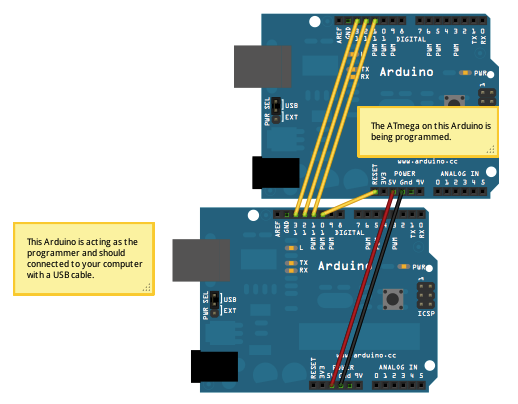 |
| Neither of the Arduinos involved look like this |
Next, plug everything in. First carefully check that the ribbon is plugged in right, then plug the Nano into USB.
Now run the bootloader instructions. All four lights on the Nano will light up simultaneously (something I hadn't seen before) and blink like crazy (except the blue power light).
 |
| Board the device and bring it to life! |
ASCII Table ~ Character Map
!, dec: 33, hex: 21, oct: 41, bin: 100001
", dec: 34, hex: 22, oct: 42, bin: 100010
#, dec: 35, hex: 23, oct: 43, bin: 100011
$, dec: 36, hex: 24, oct: 44, bin: 100100
%, dec: 37, hex: 25, oct: 45, bin: 100101
&, dec: 38, hex: 26, oct: 46, bin: 100110
', dec: 39, hex: 27, oct: 47, bin: 100111
(, dec: 40, hex: 28, oct: 50, bin: 101000
), dec: 41, hex: 29, oct: 51, bin: 101001
*, dec: 42, hex: 2A, oct: 52, bin: 101010
and so on for all 94 printable characters.
I wasn't happy with the stencil and solder paste on the edge of the board, So, on to soldering 240 surface mount LEDs by hand!
Thursday, February 23, 2012
Desktop Microscopy and Charlieplexing
One of the things I used to have to do with all my custom boards is take them into the lab at work. There they have a really nice optical microscope. This one looks at things instead of through things, so it is appropriate for electronics (funny that, being in an electronics lab). It doesn't have an eyepiece as much as it has a facepiece. The end you look through has a screen (pure optical, no electronics or cameras involved) about 5 inches wide. It gives you a stereo view with a single objective lens, because each of your eyes is looking through a different optical path in the same set of lenses.


I have been searching for something like that and finally restricted myself to something I could actually afford, a USB digital microscope. I ended up getting this microscope.
The subject of this particular set of pictures is Project Precision. For about five years now I have had a design in the back of my mind for a digital handed clock with an hour hand, minute hand, second hand and third hand (1 third = 1/60 second. Yes, really. Isaac Newton used thirds in the Principia.). I had a design using all 7400 series logic, a PIC and less 7400 logic, but finally came across the concept of charlieplexing. With 16 pins, I can control 240 LEDs. Only one at a time can be on, but I only need four on at a time, so I can strobe through those quickly enough.
 The thing is USB powered with no battery. It uses an ATmega328 as the core and an FT232 for USB-UART conversion. This basically makes it an Arduino. It has a port for a GPS receiver as well, and a couple of multiplexers to connect the ATmega, FT232, and GPS in any combination.
What I'm most proud of is the layering. I needed 60 LEDs for each hand, and with four hands, I needed the front and back of two boards. I figured out a way to make these boards identical, so when I got three copies, I had enough, and didn't have to order three copies of two different boards.
Charlieplexing involves pairs of LEDs, pointing in opposite directions. If you set one end of this combo to VCC and the other to ground, one of the pair will light. If you do it the other way, the other will light. What I have done is put half of each pair on one board, and the other half on the other board. All the LEDs on the board with the logic will point outward, while the LEDs on the other board will point inward. It's almost fate that 16 signals can control 240 LEDs, the exact number needed for four hands. 16 was the exact number of signals left on the ATmega after I accounted for the UART, clock, multiplexer controllers, etc.
Now for the tedious task of picking and placing 240 diodes... Fortunately I only have to do them 60 at a time.
No, I will not make one for you, not for any price. Well maybe, but it would have to be a lot. Better is to make one yourself.


I have been searching for something like that and finally restricted myself to something I could actually afford, a USB digital microscope. I ended up getting this microscope.
 |
| Here's what I got it for - finding solder bridges |
 |
| Really short depth of field. Do you want the top of the chip in focus... |
 |
| ...or its leads? |

What I'm most proud of is the layering. I needed 60 LEDs for each hand, and with four hands, I needed the front and back of two boards. I figured out a way to make these boards identical, so when I got three copies, I had enough, and didn't have to order three copies of two different boards.
Charlieplexing involves pairs of LEDs, pointing in opposite directions. If you set one end of this combo to VCC and the other to ground, one of the pair will light. If you do it the other way, the other will light. What I have done is put half of each pair on one board, and the other half on the other board. All the LEDs on the board with the logic will point outward, while the LEDs on the other board will point inward. It's almost fate that 16 signals can control 240 LEDs, the exact number needed for four hands. 16 was the exact number of signals left on the ATmega after I accounted for the UART, clock, multiplexer controllers, etc.
Now for the tedious task of picking and placing 240 diodes... Fortunately I only have to do them 60 at a time.
No, I will not make one for you, not for any price. Well maybe, but it would have to be a lot. Better is to make one yourself.
Monday, February 20, 2012
Loginator and SDHC progress
- All purely computing parts of the Loginator have now been tested. The power supply, USB, SD card slot, RGB light, and BOOT button all work. The charger circuit itself works, but I installed the LED backwards.
- None of the analog parts have been tested. The current sensor was originally too hot to touch when the board was on. I tried to remove it, but in the process of hitting it with the soldering iron I must have fixed it, either that or it is burned out completely. Won't know until I test the analog part. I also realized that I should have gotten the 100V/V part instead of the 20V/V part. This is fixable without any board modification.
- I may have made a foolish decision in relation to the RGB light: you can't run the lights as lights at the same time as you use the UART ports. Honestly it's not my fault. There are six PWM pins, but four of them are shared with TX and RX on the two UART ports, one is shared with the chip select pin for the card reader, and one is AD6. Right now I just use the blue and green lights, which overlap UART0. The red one overlaps TX on UART1.
- I put into the Logomatic main firmware code some compiler switches so that it can be switched to be Loginator with one switch. This controls where the code looks for the lights and STOP button. With this switch set, the Sparkfun firmware now runs on the Loginator. It is even bug compatible - the first log file is LOF01.TXT. Next is to get Logomatic Kwan adapted the same way.
- The SPI port with the SD card on it works, but I haven't tested the other SPI port or either of the I2C ports. I made a silly mistake and wired a pullup resistor to SCK1 (SPI) instead of SCL1 (I2C). I2C0 is fine, but the 11dof port uses SPI1 and I2C1, both of the affected busses. This is fixable with a green wire and a cut trace. The board modification does not require a new stencil.
- I jumped in face first with the SDHC patch and got burned. The Logomatic code now no longer creates log files. I have seen through the serial port that the code is reading the configuration file, but cannot or will not write the log file. What I will do is back out the FAT32 part and just use the new SDHC part, to start with. Once the Logomatic with SDHC works, I will update the bootloader similarly, then actually try it with an SDHC card.
- I have been looking at the LPC2468 chip. It has a purpose built SD port, DMA everywhere, USB, Ethernet if I ever wanted to use that, lots of cool new features. It's even cheaper than the LPC2148. The only problem is that it is a 208 pin chip, and I don't know if I will ever be able to solder down such a chip. Also its 28x28mm, so it may not even fit in the Logomatic board footprint. DMA is cool because it is like an arbitrary-length FIFO for every device, anywhere in memory I want it.
Thursday, February 16, 2012
Memory Dumping
I mentioned below that I had developed a method of attaching all the source code to the firmware and then having that very firmware dump itself to its log. The problem is that it takes a long long time to do this. Partly this is due to the one per second packet dump rate, and partly because hexadecimal coding doubles the data size and adding packet headers adds yet more data.
So, here's what we do. For binary packets, we just do it. Dump 64 bytes at a time into a header with 8 bytes of overhead.
For NMEA packets, we do something smart. We use Base85 encoding. This is a method of encoding 4 bytes of arbitrary binary data with no restrictions, into 5 characters carefully chosen to all be printable. Base 85 is the smallest base where 5 symbols can be used to encode the 4Gi combinations possible from 4 bytes. There are 94 printable characters, so base85 will work. Base84 won't encode 4 bytes, and Base86 doesn't gain anything.
Postscript standard Ascii85 has a couple of cool features but also a couple of drawbacks. They just use the number calculated plus 33, so as to use characters from "!" to "u". If four consecutive zero characters are transmitted, these are compressed to a single "z". If four consecutive spaces are transmitted, this goes as a "y". There are several more characters that can be used, but one of the drawbacks are that "," and "*" are used. Comma is not a killer, but star is, since it marks the end of the packet.
Since there are 94 printable characters, we can decline to use certain characters like comma and star, to fit the NMEA structure. So, one thing to do is to switch out star, and might as well do comma as well. Star turns to "v" and comma turns to "w".
The compression mentioned above is nice, but since the LPC uses NAND flash, "empty" areas are actually filled with 0xFF, not 0x00. So, we will steal "x" for encoding 4 consecutive 0xff.
Another alternative is to just make an array of 85 characters in any order that we want. We have already given up Postscript compatibility, so why be constrained by it? The Wikipedia article mentioned above mentions RFC1924, which uses 0-9, A-Z, a-z and
!#$%&()*+-;<=>?@^_`{|}~ in that order. It refrains from using ("',./:[]\) since those are harder to escape. We could choose one of those in place of star, and several other for compression.
SDHC - How do we test it?
- Compile original Logomatic firmware and install it, and see that it runs on a fat16 SD
- Compile original USB bootloader, install it, see that it runs on fat16 SD
- Modify Logomatic firmware to use new library, see that it still runs on fat16 SD
- Modify USB bootloader, install it, see that it runs on fat16 SD
- Put an SDHC card in, see if it is visible over USB
- Put a blink firmware on the SDHC and see if it is installed
- Put Logomatic firmware back on the SDHC, install it, see if it runs
- Success!
Logomatic and Loginator with SDHC and Fat32
Your Logomatic probably doesn't need fat32. It probably doesn't need more than 2GiB files or 2GiB of storage total. It probably doesn't have the battery life to support writing 2GiB.
But microSD cards that aren't SDHC are becoming hard to find. The hardware needed to interface SDHC is no different than normal microSD. It's just software. Your Logomatic (or mine for that matter, constructed in 2009) just needs a mind transplant, a simple firmware upgrade. Well, not so simple, because that firmware doesn't exist yet.
That's where I come in. I am back in the Logomatic (and Loginator, which is substantially the same) business, for the while until my attention drifts elsewhere. Hope I finish, or hope that you or someone reading can pick up where I leave off.
So, a word about the SD card software currently in the Logomatic and USB bootloader code. You can find the USB bootloader code on the Sparkfun USB bootloader tutorial, and the Logomatic firmware also on the Sparkfun site.
Remember that both of these programs are installed at the factory on each Logomatic, so you already have these in compiled form. They share no memory, but have much identical code. See, the USB bootloader needs to access the SD card, both to do the USB mass storage thing, and to check if your firmware FW.SFE file is there and read it and install it if necessary. It also has a USB driver to convert USB signals into microSD commands and vice versa. The Logomatic main firmware needs much of the same code (except for the USB part) to read its configuration files and write data to the card.
This code comes in the form of some .c files, along with supporting .h files. These files were the work of Roland Riegel, and through the magic of open source, we get to read and modify them as we see fit. As it turns out, Roland has already modified his code to handle SDHC cards, and as a logical extension, the fat32 file system. So what is left to us? Modifying this code to handle the LPC2148 chip instead of the ATmega32 that he uses. Yes, I just saw you Arduino users' ears perk up. Sorry to dissapoint, but I am not going to do anything with either Arduino or ATmega, but that doesn't mean that you can't.
So, here is how the sd-reader (as Roland calls his whole work) is structured. At its lowest level is sd_raw.c . This file is used to control the card and read and write blocks of it. This code can be used directly if you want to use the sd card without worrying about unnecessary bloatware like file systems. It also is used by the USB mass memory driver. In this case, the USB host (probably your desktop computer) sees the USB device (the Logomatic and its SD card) as a featureless sea of blocks. The USB wire protocol just concerns itself with reading and writing those blocks, along with such bookkeeping things as determining how many blocks there are. The USB driver in the LPC2148 mostly just interprets USB commands and uses the sd_raw library to fulfill these commands. The LPC2148 in this case doesn't care about filesystems. The host sees the raw blocks and it interprets them as a filesystem. In principle, this allows the host to use any filesystem it wants, without the Logomatic caring. If you wanted to, you could format the card in a Logomatic as fat16, fat32, ext4, whatever Mac uses this week, etc. We will see why this is not a good idea later.
On top of this low-level interface, we have
So how are we going to use all this code which was written for an ATmega on an LPC? That's the magic of C code and compilers. 99+% of the C code in these files will compile without change. This includes all of fat16, rootdir, and partition. These use sd_raw. Sd_raw in turn is about 99% portable as well. It knows the SD wire protocol, and how it sits on top o the SPI protocol. All it needs to know about the hardware is what registers control the SPI protocol and how to use them. This knowledge is isolated into a couple of functions, and we need only change these functions to port the code from ATmega to LPC. Almost all this code is already well-isolated, there is just one bit left that can be broken out.
More on this as I actually do it...
But microSD cards that aren't SDHC are becoming hard to find. The hardware needed to interface SDHC is no different than normal microSD. It's just software. Your Logomatic (or mine for that matter, constructed in 2009) just needs a mind transplant, a simple firmware upgrade. Well, not so simple, because that firmware doesn't exist yet.
That's where I come in. I am back in the Logomatic (and Loginator, which is substantially the same) business, for the while until my attention drifts elsewhere. Hope I finish, or hope that you or someone reading can pick up where I leave off.
So, a word about the SD card software currently in the Logomatic and USB bootloader code. You can find the USB bootloader code on the Sparkfun USB bootloader tutorial, and the Logomatic firmware also on the Sparkfun site.
Remember that both of these programs are installed at the factory on each Logomatic, so you already have these in compiled form. They share no memory, but have much identical code. See, the USB bootloader needs to access the SD card, both to do the USB mass storage thing, and to check if your firmware FW.SFE file is there and read it and install it if necessary. It also has a USB driver to convert USB signals into microSD commands and vice versa. The Logomatic main firmware needs much of the same code (except for the USB part) to read its configuration files and write data to the card.
This code comes in the form of some .c files, along with supporting .h files. These files were the work of Roland Riegel, and through the magic of open source, we get to read and modify them as we see fit. As it turns out, Roland has already modified his code to handle SDHC cards, and as a logical extension, the fat32 file system. So what is left to us? Modifying this code to handle the LPC2148 chip instead of the ATmega32 that he uses. Yes, I just saw you Arduino users' ears perk up. Sorry to dissapoint, but I am not going to do anything with either Arduino or ATmega, but that doesn't mean that you can't.
So, here is how the sd-reader (as Roland calls his whole work) is structured. At its lowest level is sd_raw.c . This file is used to control the card and read and write blocks of it. This code can be used directly if you want to use the sd card without worrying about unnecessary bloatware like file systems. It also is used by the USB mass memory driver. In this case, the USB host (probably your desktop computer) sees the USB device (the Logomatic and its SD card) as a featureless sea of blocks. The USB wire protocol just concerns itself with reading and writing those blocks, along with such bookkeeping things as determining how many blocks there are. The USB driver in the LPC2148 mostly just interprets USB commands and uses the sd_raw library to fulfill these commands. The LPC2148 in this case doesn't care about filesystems. The host sees the raw blocks and it interprets them as a filesystem. In principle, this allows the host to use any filesystem it wants, without the Logomatic caring. If you wanted to, you could format the card in a Logomatic as fat16, fat32, ext4, whatever Mac uses this week, etc. We will see why this is not a good idea later.
On top of this low-level interface, we have
- fat16.c, which knows about directories and files
- rootdir.c which sits on top of fat16 and makes it so that your code doesn't have to worry about directories
- partition.c which reads the partition table on the sd card and finds the partitions so that fat16 knows where to start.
So how are we going to use all this code which was written for an ATmega on an LPC? That's the magic of C code and compilers. 99+% of the C code in these files will compile without change. This includes all of fat16, rootdir, and partition. These use sd_raw. Sd_raw in turn is about 99% portable as well. It knows the SD wire protocol, and how it sits on top o the SPI protocol. All it needs to know about the hardware is what registers control the SPI protocol and how to use them. This knowledge is isolated into a couple of functions, and we need only change these functions to port the code from ATmega to LPC. Almost all this code is already well-isolated, there is just one bit left that can be broken out.
More on this as I actually do it...
Friday, February 3, 2012
Sparkfun AVC 2012
- The Sparkfun Air Show has been cancelled. No helicopters or quadrotors allowed. It just didn't seem like a good idea to them to have an autonomous spinning blade of death out on a course surrounded by hundreds of spectators. I support their decision, but it certainly puts a damper on my enthusiasm to build Arisa.
- I didn't buy an entry in time. I have an entry in now in backorder, but who knows if or when that will come in.
- I was too ambitious last year. When the helicopter burned out, I only had a week to try to build a car, and didn't get it done. This year, the plan is:
- Get Yukari working, which means getting the Loginator working and repairing/replacing the steering servo in the car. Yukari is done when it can drive around the school.
- Build the Secret Project. I have an idea for a robot unlike any other seen at any previous AVC. Information wants to be free, especially secret information. You only own an idea as long as you don't share it (there is no such thing as intellectual property, a subject for another post) so the Secret Project will remain secret. Even the name is secret. As if from Paranoia, the classification level of the document is also classified. This is partly because a) if you knew the name, it would reveal the design, and b) I haven't even given it a name yet.
Subscribe to:
Posts (Atom)