I have recently performed an experiment where I took the Loginator code and removed all dynamic polymorphism in place of static polymorphism. The motivation was the fact that since the sensors were all hard-wired to the board, all references to them could be figured at compile-time, and static polymorphism plus the optimizer and inliner could make "better" code. I also had an irrational fear of the vtables being corrupted.
Having gone through this exercise, I think I can say that CRTP is not the right way to do static polymorphism. It works, but it is ugly and infectious. If a class uses an object which is defined with CRTP, that class itself must also be made to use CRTP. I don't know if the machine code produced is faster, but I do know that it is significantly larger.
The motivation for changing back is the hardware description block which I am adding to the Loginator code, in hopes of being able to unify the Logomatic, Loginator, Rocketometer, Rollercoasterometer, and Pocketometer. My idea is to be able to load the same binary image into any LPC2148 based hardware I have or make, and have the software read the hardware description block to see what hardware it is attached to. This is all done at runtime, so we need dynamic polymorphism again.
CRTP isn't all bad. It works fine for instance in the dump class, where you can use it to make specializations of dump which are resolved at compile time. The problem arises when you want to pass a CRTP object as a parameter. At that point, the reference or pointer to the object has to be CRTP also, which frequently causes the whole class to need to be CRTP.
The idea then is that the general-purpose drivers are built into the code, and constructed at runtime from the hardware description block.
Showing posts with label Design. Show all posts
Showing posts with label Design. Show all posts
Friday, January 8, 2016

Tuesday, June 23, 2015
Yukari 4 and nowcasting
I have been convinced to do Yukari 4, by of all people, my lovely wife Kellie. I have a theory about what is wrong, and how to fix it with one wire and a software change.
Tuesday, June 16, 2015
Heading Reference
The hardest thing is getting an accurate heading reference. There are at least 4 possible sources:
- Magnetic compass - We are carrying one, but it is close to the motor. I'll have to check some of the data to see if the motors influence it a lot.
- Gyroscope - Subject to random walk drift and needs an accurate starting heading
- GPS heading - The GPS calculates a heading itself and reports it in RMC
- GPS delta-position - Use trigonometry and the position 1 second ago
- We initialize the gyro using "Average-G". This is the average of the last 50 gyro readings on each axis. This average is subtracted from the in-motion readings to produce a zero-biased rotation rate
- We use the first RMC sentence to get our initial heading
- Once in motion, we use the gyro as the primary heading reference. We set up an inertial frame parallel to the initial orientation of the robot, and an initial identity quaternion. We use normal quaternion integration to integrate the gyro readings and get a new gyro-based orientation. We use that orientation to transform the vector pointing forward (the nose vector) from the body to the reference frame. The gyro heading is then the angle between the initial nose vector (same as the body nose vector) and the current nose vector. We use the initial heading to calculate the offset between the gyro heading and true north, and add this offset to the gyro heading to get the instantaneous heading relative to true north
- Whenever a large maneuver is executed, IE a large yaw rate is sensed, a countdown is set to 400 readings (4 seconds). When this countdown expires, we use method 4 to get the heading if the speed of the vehicle is high enough. We use this heading to calculate a new heading offset.
- We know the initial heading from the first two waypoints. Provided the robot is accurately aimed toward the waypoint, it will be plenty good enough.
- We are going to add a green button. Before the button is pushed, the robot will continually be recording the gyro readings, but will remember the last 50. Each reading, we will pop one reading out of the queue, and average it with the running total. The weighting will be 1 point for the new reading and 49 for the old average. In effect this takes the average of all the measurements from robot reset, but each old measurement has an exponentially decaying weight. We include some code to wait for 49 measurements before using a weighting of 49. We remember 50 measurements because the very act of pushing the green button will cause the robot to shake and will ruin the current measurements.
Thursday, July 3, 2014
Cleaning up the code
"All the most important mistakes on a project are made on the first day"
--Old design adage
"There is no teacher but the enemy. No one but the enemy will tell you what the enemy is going to do. No one but the enemy will ever teach you how to destroy and conquer. Only the enemy shows you where you are weak. Only the enemy tells you where he is strong. And the only rules of the game are what you can do to him and what you can stop him from doing to you."
-- Mazer Rackham
"Reinhardt regarded the mysteries of the Universe not as indifferent questions of physics or chemistry, but as implacable, malicious foes. They were to be assaulted with science, vanquished at any cost, forced to yield their treasure house of knowledge."
-- from The Black Hole by Alan Dean Foster
In any interesting problem, you don't know enough about the problem to begin with to even form a plan for solving it. You do the best you can, and in the process of solving the problem, you learn what you should have been doing from the beginning. If time and resources weren't an obstacle, you could go back and solve the problem right from the beginning. But, usually for any interesting problem, time and resources are an obstacle, and you are stuck with what you started with. At each point in solving the problem, you only change what came before to the absolute minimum degree necessary.
As a result, sometimes legacy design choices make the solution quite a bit more complicated than a clean solution would be.
Now I have time and resources -- a whole year of time. It's time to clean house.
--Old design adage
"There is no teacher but the enemy. No one but the enemy will tell you what the enemy is going to do. No one but the enemy will ever teach you how to destroy and conquer. Only the enemy shows you where you are weak. Only the enemy tells you where he is strong. And the only rules of the game are what you can do to him and what you can stop him from doing to you."
-- Mazer Rackham
"Reinhardt regarded the mysteries of the Universe not as indifferent questions of physics or chemistry, but as implacable, malicious foes. They were to be assaulted with science, vanquished at any cost, forced to yield their treasure house of knowledge."
-- from The Black Hole by Alan Dean Foster
In any interesting problem, you don't know enough about the problem to begin with to even form a plan for solving it. You do the best you can, and in the process of solving the problem, you learn what you should have been doing from the beginning. If time and resources weren't an obstacle, you could go back and solve the problem right from the beginning. But, usually for any interesting problem, time and resources are an obstacle, and you are stuck with what you started with. At each point in solving the problem, you only change what came before to the absolute minimum degree necessary.
As a result, sometimes legacy design choices make the solution quite a bit more complicated than a clean solution would be.
Now I have time and resources -- a whole year of time. It's time to clean house.
Wednesday, June 6, 2012
A new weapon in the war against Bugs and Photino Birds
Keil μVision 4 Debugger/Simulator. This is a small part of the larger (450MB, really guys?) μVision suite, but the only part I care about. With it I was able to debug my Task code, which is interesting given that I did not write or compile my code in μVision. Get the program and install it (it installs fine under Wine on Linux) and then bring up any example project, compile it, and get into debug mode. Then, right-click the disassembly window and select "Load Hex or Object File...". Now select the master .elf file that was compiled with GnuARM. It will load, and the simulated processor will be reset, so it starts at location 0 (of your code, apparently it skips the ISP).
And now for a word (or thousand) about tasks...
And now for a word (or thousand) about tasks...
Wednesday, May 9, 2012
Designing a large charlieplex
I saw a new cool way to design a charlieplex, one which is easy and obvious, even for an extremely large LED matrix. This was buried in a post below where I blather on about my own problems, so I broke it out into a post that Google is more likely to find.
Tuesday, March 27, 2012
LPC2368
I have a new favorite microcontroller: the LPC2368. It programs similar to the LPC2148 but is much more "digital" and much less "analog". It has four UARTs, three SPI ports, three I2C ports, something called I2S, two CAN ports (maybe I can talk to my car, or more like listen to it), two USBs, an ethernet port(!) and so on and so on. One big deal is a hardware SD/MMC port. My previous new love was the 2468, but that one has 208 pins and probably wouldn't fit on the Logomatic footprint, much less the stick IMUinator.
This guy has exactly 100 pins. The one big feature that the 2368 lacks is an external memory interface. That and a lot more GPIO pins. For two main reasons, the 2368 is more convenient to work with than the 2148:
All the sensors I plan on using now and in the future are digital anyway, so to me, losing A/D is no big loss.
Also, all the peripherals except I2C have DMA, which I think means you can hand them a big block of data (or tell them to listen for a big block of data) and then the peripheral will take care of itself, while the core continues its programs. No more busy waits for the SD card.
I am working on a Loginator2368 which is increasingly less pin-compatible with the Loginator, but still roughly the same shape and size. Who knows if it can be made to fit on a Stick IMUinator?
This guy has exactly 100 pins. The one big feature that the 2368 lacks is an external memory interface. That and a lot more GPIO pins. For two main reasons, the 2368 is more convenient to work with than the 2148:
- More pins means less overlap between functions. Several of the peripherals have dedicated pins (Ethernet, one I2C) so there is no problem with overlap. PWM and UART still overlap, but there are enough pins and two choices for each overlap that you can use all 6 PWMs and all of the UARTS.
- Fewer analog inputs, so those don't take as many pins.
All the sensors I plan on using now and in the future are digital anyway, so to me, losing A/D is no big loss.
Also, all the peripherals except I2C have DMA, which I think means you can hand them a big block of data (or tell them to listen for a big block of data) and then the peripheral will take care of itself, while the core continues its programs. No more busy waits for the SD card.
I am working on a Loginator2368 which is increasingly less pin-compatible with the Loginator, but still roughly the same shape and size. Who knows if it can be made to fit on a Stick IMUinator?
Tuesday, February 28, 2012
Drat!!!
Lights 4 and 5 on the back of the second board (where I am installing the blue lights) won't light. As it happens, neither will any of 54-59, but we'll save that part of the story for later.
I remember the solder bridge between two pins, and one of those pins, A7, is involved with the lights that don't work. So, we carefully measure pin A7 and conclude that no matter how we program it, it acts like a high impedance. The natural conclusion is that it is burned out. So, run to Sparkfun, buy their last three ATmega328s, and a hot air rework station to pull the old chip. Carefully remove the old chip, taking care not to scorch the white paint on the board or blow away any of the passive components. When the chip comes off, it comes off great. Put in a new chip, verrrry carefully check continuity between each pin to make sure there are no bridges or missed joints. Fix a couple of missed joints. Guess what. The board acts exactly as it did.
So, that theory is shot. I might have burned out pins on this chip, but exactly the same pins? I think not. Now time to gather more evidence for another theory. Write up a program that listens for commands on the serial port and turns individual signals high or low, with the rest at high-Z. Signals 1 and 16 are both no good. What is going on?
The Arduino documentation says that you can use the analog input pins A0... as normal digital pins with the syntax pinMode(A0,OUTPUT); digitalWrite(A0,HI); etc. Which is in fact true, but only to a point. On an ATmega328, pins A6 and A7 are internally called ADC6 and ADC7, not PB...(ADC6) or anything like that. They are dedicated input pins. I had been planning (as in had a circut board made) to use A6 and A7 as Charlieplex lines 1 and 16. Guess which Charlieplex lines don't work... And guess which signals lights 4 and 5 (and 54-59) use...
I have no one to blame for this but myself. It was right on the Eagle schematic symbol the whole time that all the other A0... pins were secondary uses of GPIO pins, but A6 and A7 were only labeled as ADC. I guess the weird part is that the crystal inputs and reset line are alternate uses of GPIO lines, but A6 and A7 are not.
So, here's the plan. Lots of green wires, hot air, and razor blades, to hack D11 and D12 into P1 and P16. This will require giving up two multiplexers, which completely hashes my plan to use the GPS. At least this will let me test the charlieplex. Then, order 16 more blue lights, another FT232 and a correctly wired board which uses the crystal pins as two more digital outputs, allowing me to use D11 and D12 as multiplexer controllers on the next rev. NO getting a new board until all the green wires are fixed. Don't even touch Eagle until the last green wire is in place and CharlieTest works. Consider putting a LiPo battery power supply on the next board as well.
The moral of the story is keep working the problem until you find the problem, and don't guess. I have a nice new hot air rework station which works really well, and costs more than the LEDs combined. Oh well.
I remember the solder bridge between two pins, and one of those pins, A7, is involved with the lights that don't work. So, we carefully measure pin A7 and conclude that no matter how we program it, it acts like a high impedance. The natural conclusion is that it is burned out. So, run to Sparkfun, buy their last three ATmega328s, and a hot air rework station to pull the old chip. Carefully remove the old chip, taking care not to scorch the white paint on the board or blow away any of the passive components. When the chip comes off, it comes off great. Put in a new chip, verrrry carefully check continuity between each pin to make sure there are no bridges or missed joints. Fix a couple of missed joints. Guess what. The board acts exactly as it did.
So, that theory is shot. I might have burned out pins on this chip, but exactly the same pins? I think not. Now time to gather more evidence for another theory. Write up a program that listens for commands on the serial port and turns individual signals high or low, with the rest at high-Z. Signals 1 and 16 are both no good. What is going on?
The Arduino documentation says that you can use the analog input pins A0... as normal digital pins with the syntax pinMode(A0,OUTPUT); digitalWrite(A0,HI); etc. Which is in fact true, but only to a point. On an ATmega328, pins A6 and A7 are internally called ADC6 and ADC7, not PB...(ADC6) or anything like that. They are dedicated input pins. I had been planning (as in had a circut board made) to use A6 and A7 as Charlieplex lines 1 and 16. Guess which Charlieplex lines don't work... And guess which signals lights 4 and 5 (and 54-59) use...
I have no one to blame for this but myself. It was right on the Eagle schematic symbol the whole time that all the other A0... pins were secondary uses of GPIO pins, but A6 and A7 were only labeled as ADC. I guess the weird part is that the crystal inputs and reset line are alternate uses of GPIO lines, but A6 and A7 are not.
So, here's the plan. Lots of green wires, hot air, and razor blades, to hack D11 and D12 into P1 and P16. This will require giving up two multiplexers, which completely hashes my plan to use the GPS. At least this will let me test the charlieplex. Then, order 16 more blue lights, another FT232 and a correctly wired board which uses the crystal pins as two more digital outputs, allowing me to use D11 and D12 as multiplexer controllers on the next rev. NO getting a new board until all the green wires are fixed. Don't even touch Eagle until the last green wire is in place and CharlieTest works. Consider putting a LiPo battery power supply on the next board as well.
The moral of the story is keep working the problem until you find the problem, and don't guess. I have a nice new hot air rework station which works really well, and costs more than the LEDs combined. Oh well.
Thursday, February 23, 2012
Desktop Microscopy and Charlieplexing
One of the things I used to have to do with all my custom boards is take them into the lab at work. There they have a really nice optical microscope. This one looks at things instead of through things, so it is appropriate for electronics (funny that, being in an electronics lab). It doesn't have an eyepiece as much as it has a facepiece. The end you look through has a screen (pure optical, no electronics or cameras involved) about 5 inches wide. It gives you a stereo view with a single objective lens, because each of your eyes is looking through a different optical path in the same set of lenses.


I have been searching for something like that and finally restricted myself to something I could actually afford, a USB digital microscope. I ended up getting this microscope.
The subject of this particular set of pictures is Project Precision. For about five years now I have had a design in the back of my mind for a digital handed clock with an hour hand, minute hand, second hand and third hand (1 third = 1/60 second. Yes, really. Isaac Newton used thirds in the Principia.). I had a design using all 7400 series logic, a PIC and less 7400 logic, but finally came across the concept of charlieplexing. With 16 pins, I can control 240 LEDs. Only one at a time can be on, but I only need four on at a time, so I can strobe through those quickly enough.
 The thing is USB powered with no battery. It uses an ATmega328 as the core and an FT232 for USB-UART conversion. This basically makes it an Arduino. It has a port for a GPS receiver as well, and a couple of multiplexers to connect the ATmega, FT232, and GPS in any combination.
What I'm most proud of is the layering. I needed 60 LEDs for each hand, and with four hands, I needed the front and back of two boards. I figured out a way to make these boards identical, so when I got three copies, I had enough, and didn't have to order three copies of two different boards.
Charlieplexing involves pairs of LEDs, pointing in opposite directions. If you set one end of this combo to VCC and the other to ground, one of the pair will light. If you do it the other way, the other will light. What I have done is put half of each pair on one board, and the other half on the other board. All the LEDs on the board with the logic will point outward, while the LEDs on the other board will point inward. It's almost fate that 16 signals can control 240 LEDs, the exact number needed for four hands. 16 was the exact number of signals left on the ATmega after I accounted for the UART, clock, multiplexer controllers, etc.
Now for the tedious task of picking and placing 240 diodes... Fortunately I only have to do them 60 at a time.
No, I will not make one for you, not for any price. Well maybe, but it would have to be a lot. Better is to make one yourself.


I have been searching for something like that and finally restricted myself to something I could actually afford, a USB digital microscope. I ended up getting this microscope.
 |
| Here's what I got it for - finding solder bridges |
 |
| Really short depth of field. Do you want the top of the chip in focus... |
 |
| ...or its leads? |

What I'm most proud of is the layering. I needed 60 LEDs for each hand, and with four hands, I needed the front and back of two boards. I figured out a way to make these boards identical, so when I got three copies, I had enough, and didn't have to order three copies of two different boards.
Charlieplexing involves pairs of LEDs, pointing in opposite directions. If you set one end of this combo to VCC and the other to ground, one of the pair will light. If you do it the other way, the other will light. What I have done is put half of each pair on one board, and the other half on the other board. All the LEDs on the board with the logic will point outward, while the LEDs on the other board will point inward. It's almost fate that 16 signals can control 240 LEDs, the exact number needed for four hands. 16 was the exact number of signals left on the ATmega after I accounted for the UART, clock, multiplexer controllers, etc.
Now for the tedious task of picking and placing 240 diodes... Fortunately I only have to do them 60 at a time.
No, I will not make one for you, not for any price. Well maybe, but it would have to be a lot. Better is to make one yourself.
Thursday, February 16, 2012
Memory Dumping
I mentioned below that I had developed a method of attaching all the source code to the firmware and then having that very firmware dump itself to its log. The problem is that it takes a long long time to do this. Partly this is due to the one per second packet dump rate, and partly because hexadecimal coding doubles the data size and adding packet headers adds yet more data.
So, here's what we do. For binary packets, we just do it. Dump 64 bytes at a time into a header with 8 bytes of overhead.
For NMEA packets, we do something smart. We use Base85 encoding. This is a method of encoding 4 bytes of arbitrary binary data with no restrictions, into 5 characters carefully chosen to all be printable. Base 85 is the smallest base where 5 symbols can be used to encode the 4Gi combinations possible from 4 bytes. There are 94 printable characters, so base85 will work. Base84 won't encode 4 bytes, and Base86 doesn't gain anything.
Postscript standard Ascii85 has a couple of cool features but also a couple of drawbacks. They just use the number calculated plus 33, so as to use characters from "!" to "u". If four consecutive zero characters are transmitted, these are compressed to a single "z". If four consecutive spaces are transmitted, this goes as a "y". There are several more characters that can be used, but one of the drawbacks are that "," and "*" are used. Comma is not a killer, but star is, since it marks the end of the packet.
Since there are 94 printable characters, we can decline to use certain characters like comma and star, to fit the NMEA structure. So, one thing to do is to switch out star, and might as well do comma as well. Star turns to "v" and comma turns to "w".
The compression mentioned above is nice, but since the LPC uses NAND flash, "empty" areas are actually filled with 0xFF, not 0x00. So, we will steal "x" for encoding 4 consecutive 0xff.
Another alternative is to just make an array of 85 characters in any order that we want. We have already given up Postscript compatibility, so why be constrained by it? The Wikipedia article mentioned above mentions RFC1924, which uses 0-9, A-Z, a-z and
So, here's what we do. For binary packets, we just do it. Dump 64 bytes at a time into a header with 8 bytes of overhead.
For NMEA packets, we do something smart. We use Base85 encoding. This is a method of encoding 4 bytes of arbitrary binary data with no restrictions, into 5 characters carefully chosen to all be printable. Base 85 is the smallest base where 5 symbols can be used to encode the 4Gi combinations possible from 4 bytes. There are 94 printable characters, so base85 will work. Base84 won't encode 4 bytes, and Base86 doesn't gain anything.
Postscript standard Ascii85 has a couple of cool features but also a couple of drawbacks. They just use the number calculated plus 33, so as to use characters from "!" to "u". If four consecutive zero characters are transmitted, these are compressed to a single "z". If four consecutive spaces are transmitted, this goes as a "y". There are several more characters that can be used, but one of the drawbacks are that "," and "*" are used. Comma is not a killer, but star is, since it marks the end of the packet.
Since there are 94 printable characters, we can decline to use certain characters like comma and star, to fit the NMEA structure. So, one thing to do is to switch out star, and might as well do comma as well. Star turns to "v" and comma turns to "w".
The compression mentioned above is nice, but since the LPC uses NAND flash, "empty" areas are actually filled with 0xFF, not 0x00. So, we will steal "x" for encoding 4 consecutive 0xff.
Another alternative is to just make an array of 85 characters in any order that we want. We have already given up Postscript compatibility, so why be constrained by it? The Wikipedia article mentioned above mentions RFC1924, which uses 0-9, A-Z, a-z and
!#$%&()*+-;<=>?@^_`{|}~ in that order. It refrains from using ("',./:[]\) since those are harder to escape. We could choose one of those in place of star, and several other for compression.
Sunday, October 16, 2011
Power Supply
Or: You can't use an N-channel MOSFET as a high-side switch.
Update: NXP finally released an app note detailing what each part is for: AN11392 - Guidelines for full-speed USB on NXP's LPC microcontrollers (19 Feb 2014). Some of what I guessed below is right, while some is misleading, and it appears that the Sparkfun circuit doesn't even follow the specification. Notes above in my 2 Apr 2014 entry.
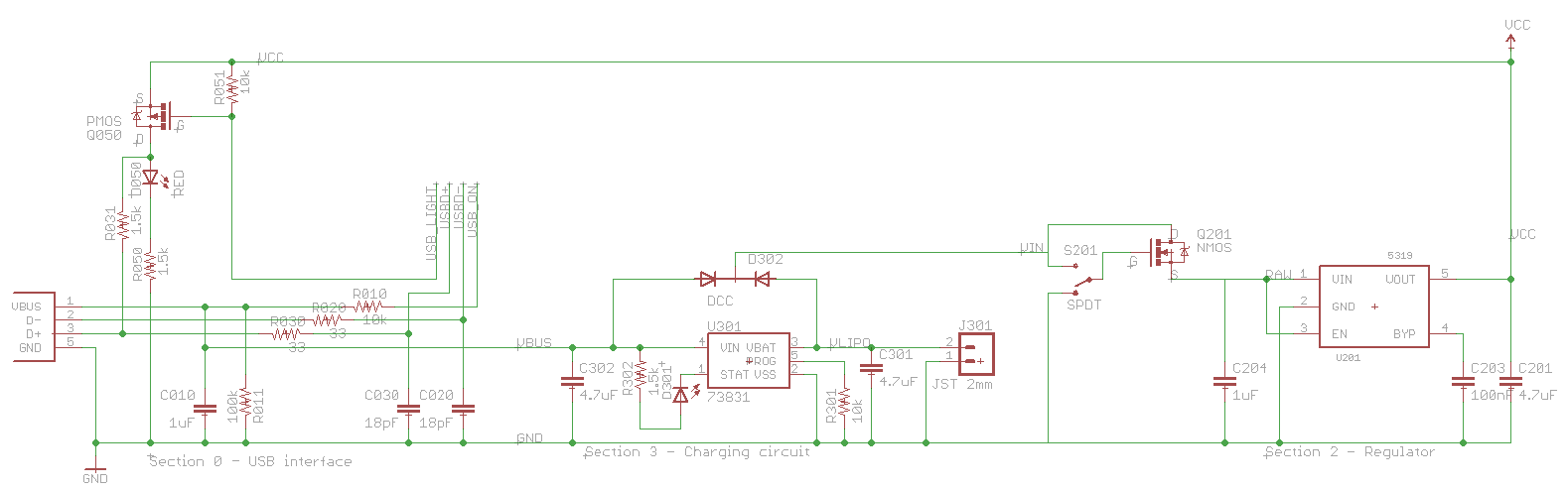
I am trying very hard to use all of my components within their specifications. One part that was having trouble was the power switch in the power supply.
First, a look at the power supply:
 This is cool because I can finally explain each and every part in the USB circuit, something that I haven't seen online yet.
Let's take a closer look at the USB part:
 All the parts are R0xx, C0xx, and so on because they are in section 0 of the board. The 10's digit specifies which main pin of the USB jack they are associated with, so for example R010 is associated with pin 1 (Vbus).
For Google, this is the USB to LPC2148 SOFTCONNECT INTERFACE
Parts list:
A bit about the genealogy of this circuit. I originally got it from the Sparkfun Logomatic, which apparently was adapted from the Keil MCB2140 board, as explained by microbuilder.eu. All of these parts have a bunch of stuff not explained anywhere, and not mentioned on the LPC2148 datasheet, as seen below:
 The Keil design combines the best features of these two suggestions, mostly using the top design but putting an LED in and implementing the switch with a PNP transistor.
I have made some further adaptations to reduce the pin count and eliminate the vile BJT transistor in favor of a good and virtuous FET. Someday I will explain why FETs are better, but they are. Use FETs when you can, and BJTs when you have to.
So, in part number order:
On to the charging circuit. I use an MCP73831, programmed to charge at 100mA, since I am planning for a battery as small as 100mAh. I have added a diode network D302 since there is no clear description in the data sheet for the 73831 explaining what the circuit will do if there is USB power present but no battery. With this diode network, if USB is present but the battery is not, the USB line will directly power the load. If the battery is present but the USB is not, the battery will power the load. If both are present, the USB wins, and the charger just has to concern itself with the battery, not the load.
Finally, the regulator circuit, and why this entry is subtitled "You can't use an N-channel MOSFET as a high-side switch."
The regulator itself is a MIC5319, capable in principle of delivering 500mA. Not that this is needed with the IMUinator, but to provide for future design expansion. It is hooked up exactly as specified in its own datasheet. The interesting part is the switch between the regulator and battery. That switch is only rated for 100mA. So, I said, let's stick a FET in there. We pick a nice high-current, low resistance FET available in a SOT-23 package. Use the switch to turn on the FET, and the FET to turn on the resistor. And here is where I made my mistake. I chose an N-channel FET, because I wanted direct logic on the switch (switch on -> FET on) and I installed it on the high side so that the circuit would be grounded (except for a floating Vin) when the FET was off.
But, "You can't use an N-channel MOSFET as a high-side switch".The FET is more accurately a voltage-controlled resistor. When the gate-to-source voltage is high enough, the resistance drops, and effectively the FET is just a wire, with about 200mΩ of resistance. But, the voltage is gate-to-source, and the very fact of dropping resistance raises the source-to-ground voltage. The gate-to-ground voltage remains the same, but the gate-to-source voltage drops as the source-to-ground voltage rises. The switch turns itself off.
It's not quite this bad, but in a way it is worse. The device will find some stable in-between state, dependent on the voltage supplied and probably the load on the regulator output. This in-between state will not be high enough to actually do anything, but high enough to draw some power, and dissipate it right in the FET. With the USB plugged in, the input was about 4.67V and I was getting about 3.07V out of a 3.3V regulator, showing that the FET had stabilized at less than 3.3V, when I was expecting near 4.67V. When the battery was used, the value was about 2.7V, not even enough to run the LPC2148.
So, the possible solutions are:
Update the second 24 Apr 2013:
Update: NXP finally released an app note detailing what each part is for: AN11392 - Guidelines for full-speed USB on NXP's LPC microcontrollers (19 Feb 2014). Some of what I guessed below is right, while some is misleading, and it appears that the Sparkfun circuit doesn't even follow the specification. Notes above in my 2 Apr 2014 entry.
I am trying very hard to use all of my components within their specifications. One part that was having trouble was the power switch in the power supply.
First, a look at the power supply:
Let's take a closer look at the USB part:

For Google, this is the USB to LPC2148 SOFTCONNECT INTERFACE
Parts list:
| Quantity | Digikey Part | Value | Device | Part Numbers |
|---|---|---|---|---|
| 2 | 490-1281-1-ND | 18pF | CAP0402-CAP | C020, C030 |
| 1 | 490-3890-1-ND | 1μF | CAP0402-CAP | C010 |
| 1 | 350-2029-1-ND | RED | LED0603 | D050 |
| 1 | 455-2562-1-ND | USB_MICROB_JST | USB_MICROB_JST | J001 |
| 1 | BSS84-FDICT-ND | PMOS | MOSFET-PCHANNELSMD | Q050 |
| 2 | P10.0KLCT-ND | 10k | RESISTOR0402-RES | R010, R051 |
| 1 | P100KLCT-ND | 100k | RESISTOR0402-RES | R011 |
| 2 | P33.0LCT-ND | 33 | RESISTOR0402-RES | R020, R030 |
| 2 | P1.50KLCT-ND | 1.5k | RESISTOR0402-RES | R031, R050 |
A bit about the genealogy of this circuit. I originally got it from the Sparkfun Logomatic, which apparently was adapted from the Keil MCB2140 board, as explained by microbuilder.eu. All of these parts have a bunch of stuff not explained anywhere, and not mentioned on the LPC2148 datasheet, as seen below:

I have made some further adaptations to reduce the pin count and eliminate the vile BJT transistor in favor of a good and virtuous FET. Someday I will explain why FETs are better, but they are. Use FETs when you can, and BJTs when you have to.
So, in part number order:
- C010 is required by the USB spec. There must be between 1μF and 10μF between Vbus and Gnd as seen from upstream. If there is too little, the downstream device could be damaged by inductive flyback from the wire as it is disconnected. If there is too much, the inrush current to charge all that capacitance will be too high. The Sparkfun circuit had 0.1μF here, seemingly out of spec, but as it turns out, some of the capacitors downstream in the charger circuit are visible also. The Sparkfun circuit as a whole is within specs. This capacitor used to be higher until I noticed all the capacitance visible downstream.
- R010 and R011 seem to be there to provide pull-up and pull-down if the USB plug is unplugged or shorted. If the plug is unplugged, there is a total of 110kΩ of pull-down, so that the pin has a defined non-floating value if it is input. If Vbus and Gnd are shorted, there is still 10kΩ of pull-down, and more importantly, if the controller pin is output and high, there is 10kΩ of current limit.
- R020 and R030 are required by the USB spec. There must be between 28Ω and 44Ω of termination resistance. Accounting for the internals of the LPC2148, there must be a 33Ω resistor in series with each data line, as called out by the data sheet above.
- C020 and C030, form the other half of a low-pass noise filter, when combined with R020 and R030. In this case, frequencies higher than 250MHz are filtered out. This prevents the channel from being used as a high-speed (480MHz) channel, but the LPC2148 isn't capable of this anyway.
- R031 is required by the USB spec. When the downstream device (in this case the LPC2148) is ready to communicate, it ties in a pull-up resistor to one of D- (if low-speed) or D+ (if full-speed). Since the LPC2148 is a full-speed device (12MHz, up to 12Mb/s) it ties to D+.
- Q050 is the SoftConnect switch. It is a P-channel FET used as a high-side switch, which takes a bit of explanation. In a P-channel device, the source is connected to high voltage, and the drain to ground. If the gate voltage is sufficiently lower than the source, the FET conducts. In this circuit, the source is connected to Vcc (3.3V) and the gate is connected to the USB_SOFTCONNECT (or USB_LIGHT) pin on the LPC2148. When that pin is low, the transistor turns on, and provides a low-resistance path to Vcc, in effect tying one end of R031 to Vcc, which tells the upstream host that this device is ready to communicate. When the pin is high, the transistor turns off, and that end of R031 is left floating.
- D050 and R050 form an LED chain which lights whenever Q050 is on, or in other words, when SoftConnect is activated.
- R051 is a pull-up resistor, so that when the LPC2148 is off or its SoftConnect pin is input (as it is just after reset) the transistor is off, since its gate is not floating.
On to the charging circuit. I use an MCP73831, programmed to charge at 100mA, since I am planning for a battery as small as 100mAh. I have added a diode network D302 since there is no clear description in the data sheet for the 73831 explaining what the circuit will do if there is USB power present but no battery. With this diode network, if USB is present but the battery is not, the USB line will directly power the load. If the battery is present but the USB is not, the battery will power the load. If both are present, the USB wins, and the charger just has to concern itself with the battery, not the load.
Finally, the regulator circuit, and why this entry is subtitled "You can't use an N-channel MOSFET as a high-side switch."
The regulator itself is a MIC5319, capable in principle of delivering 500mA. Not that this is needed with the IMUinator, but to provide for future design expansion. It is hooked up exactly as specified in its own datasheet. The interesting part is the switch between the regulator and battery. That switch is only rated for 100mA. So, I said, let's stick a FET in there. We pick a nice high-current, low resistance FET available in a SOT-23 package. Use the switch to turn on the FET, and the FET to turn on the resistor. And here is where I made my mistake. I chose an N-channel FET, because I wanted direct logic on the switch (switch on -> FET on) and I installed it on the high side so that the circuit would be grounded (except for a floating Vin) when the FET was off.
But, "You can't use an N-channel MOSFET as a high-side switch".The FET is more accurately a voltage-controlled resistor. When the gate-to-source voltage is high enough, the resistance drops, and effectively the FET is just a wire, with about 200mΩ of resistance. But, the voltage is gate-to-source, and the very fact of dropping resistance raises the source-to-ground voltage. The gate-to-ground voltage remains the same, but the gate-to-source voltage drops as the source-to-ground voltage rises. The switch turns itself off.
It's not quite this bad, but in a way it is worse. The device will find some stable in-between state, dependent on the voltage supplied and probably the load on the regulator output. This in-between state will not be high enough to actually do anything, but high enough to draw some power, and dissipate it right in the FET. With the USB plugged in, the input was about 4.67V and I was getting about 3.07V out of a 3.3V regulator, showing that the FET had stabilized at less than 3.3V, when I was expecting near 4.67V. When the battery was used, the value was about 2.7V, not even enough to run the LPC2148.
So, the possible solutions are:
- Use a P-channel FET. This is what I would do if I had caught the design flaw early enough. The circuit would be identical, just the opposite switch position would now be on. Unfortunately, P-channel FETs and N-channel FETs both have the same pin assignments, so the source on the P-channel is the same pin as the source on the N-channel. However, the P-channel FET needs to have its source connected to high voltage, not low, so the board design would have to change. Since I already waited almost three weeks for the board, I can't do this.
- Remove the FET entirely. This way we just connect the gate terminal on the board to the source, and use the mechanical switch as the main switch. Perfect if I could just remove that FET already soldered on the board, or if I built a new one with no FET, but I don't have those parts.
- Short the FET. Don't remove it, just put a wire over the FET from gate to source. This will guarantee the gate-to-source voltage is zero, and therefore that the FET is off all the time. In the mean time, the voltage applied to the gate is shorted past the source to the load.
Update the second 24 Apr 2013:
Thursday, September 22, 2011
Eagle autorouter tips
It's pretty easy to comb the net for trash-talk and criticism of the CadSoft Eagle autorouter. Honestly it's not very good. It's less good than I am at routing, and I'm not that good.
But, if you lack patience like I do, the autorouter is the way to go. You can set it loose on a problem, go get a soda, read some blogs, come back, and have an acceptable if not beautiful board.
I have gathered a couple of useful hints which has helped the success of my autorouting attempts enormously:
But, if you lack patience like I do, the autorouter is the way to go. You can set it loose on a problem, go get a soda, read some blogs, come back, and have an acceptable if not beautiful board.
I have gathered a couple of useful hints which has helped the success of my autorouting attempts enormously:
- Do a good job placing components. Consider the hardware subroutine advice below.
- Set the routing grid to a very small number. If you are using inches, set it to 1 mil. I think the routing time goes up with the inverse square of the grid size, so half the grid size takes four times longer, but often the router can find solutions with a smaller grid that elude it with a larger grid.
- Consider the shape of your board, and the general "grain" of the signals on it. On long, skinny boards like the Stick IMUinator, it may not be best to prefer horizontal and vertical. Most of your signals will want to go horizontal, forcing most of them to one side of the board. Consider doing the preferred directions diagonally. I learned this by watching the FreeRouting.net autorouter work on my design.
- Delete (not just rip up) your ground plane polygons. The autorouter doesn't seem to handle polygons well at all, but if the polygon is not there and it treats ground just like any other signal, it can usually handle it well.
- Be prepared to do a manual cleanup after the autorouter is done. Put back the ground planes, and rip up all the lines, but not the vias, in the ground signal. Sometimes, you will find it necessary to leave a wire which connects parts of the ground plane. This especially happens if your ground planes use thermals. Also just fix any general ugliness on the board. For instance, the autorouter loves to bring a signal out the side of a QFP pad (like on the controller in the IMUinator) and bring it as close as possible to another pin before turning. Fix these manually.
- Check if the router has done anything monumentally stupid. For instance on the Stick IMUinator, the main crystal has four pads, two of which need to be grounded and two which are the crystal terminals. These are diagonally opposed, so that the orientation of the crystal doesn't matter. But, the autorouter connected the two ground terminals across the middle of the part, leaving no space for the actual crystal terminals. So, it routed one crystal terminal over the river, through the woods, past Grandmother's house, and ended up with a signal about 10x longer than the other one on both sides of the board, braided with other signals for maximum crosstalk problems. To fix this, I ripped it all up, manually routed just the crystal signals, then let the autorouter have at it.
Thursday, September 15, 2011
Hardware is not Software 1
As many of my readers know, I am working on an IMU suitable to be put into rockets, robots, smuggled onto rollercoasters, etc.
I took a quick trip to the local hobby store (I love living in Longmont, 3 blocks from HobbyTown USA) to check out the rockets which were payload capable. I was looking for something a bit smaller and more manageable than the Big Daddy. What I found is that all the payloaders had a payload bay of 1.0" diameter or larger. If I made the IMU narrower than 1.0", I could fit most rockets.
So, Gentlemen, Behold! The Stick IMUinator!

This board is 0.9" x 2.0" and includes:
Now, why is this post titled "Hardware is not Software"? Well, I had what I thought was a briliant idea at the time. I couldn't get the Eagle autorouter to work well with such a tightly packed board. So, my briliant idea was to lay out the board in sections:
The next step is to lay out each section on the board, independently. Here is where hardware is different than software. My idea was to lay out each section, get it as small and compact as I could, then put all the sections together. Each section would have its interface with the outside through a small single set of signals. Each interface would be represented in the section by a surface-mount part with 6mil pads spaced 6mil apart. For instance, the USB section had one interface with four signals, USB presence, D+, D-, and SoftConnect. So, I put down an interface part with four pins and ran those signals to those pins. Vbus was connected to a different single-pin interface. Ground was left free-roaming.
Each section except for section 4 would be completely manually routed. All the parts are carefully laid out in their sections. I was able to get the power supply (sections 0, 2, and 3) on the back of the board and with a single layer of traces. This left the other side of the board available for something large in area but simple in layout. I wanted the sensors, particularly the compass, as far from the power supply as possible. The MicroSD slot turned out to be the perfect part.
Section 4, the controller, interfaced with everything else, so it was the most complicated. I hand-routed the crystal, USB, and SPI0 interface, but just plopped down some interface parts for the rest and let the autorouter have at it.
Now any programmers out there immediately recognize my attempt a hardware subroutines. The idea is to break a problem down into smaller, easier-to-solve parts. Each part interacts with the other parts through a well-defined, reusable interface.
Well, in hardware you can't quite do that. In a sense, that's what ICs are, but anyone who has laid out a board with multiple ICs has scratched their heads and said, "Why in the world did they order the pins that way?" You just can't optimize hardware and maintain the clean interface. For instance, when laying out the controller, I had to plan which direction to orient it. This was dependent on where the other sections were, so this hardware layout of the controller is dependent on this particular hardware.
Finally I put all the sections together and wired together their interfaces. This is where I discovered why in the world they put the pins in the order they did. Sometimes you can optimize the routing of a section by re-ordering the pins. Only rarely does this re-ordering match what was done to the matching interface on the other section. So, you have to plan in space for the interface, including the necessary vias and other-side board space to get signals across each other.
Ultimately I had a layout I was happy with. I then took a leap of faith. I ripped up all the routes and let the autorouter have a crack a the whole board at once. It wasn't actually that big of a risk, as I knew that there was a solution. Now the autorouter had no trouble, mostly because all the parts were well laid out. It ended up with a better design than I had before. So, this works, but not quite like I planned it.
Summary of steps:
I took a quick trip to the local hobby store (I love living in Longmont, 3 blocks from HobbyTown USA) to check out the rockets which were payload capable. I was looking for something a bit smaller and more manageable than the Big Daddy. What I found is that all the payloaders had a payload bay of 1.0" diameter or larger. If I made the IMU narrower than 1.0", I could fit most rockets.
So, Gentlemen, Behold! The Stick IMUinator!

This board is 0.9" x 2.0" and includes:
- ADXL345 3-axis accelerometer, digital readout over SPI/I2C
- L3G4200D 3-axis rotation rate sensor, digital readout over SPI
- BMP085 barometric pressure and temperature sensor, digital readout over I2C
- HMC5883 3-axis magnetic sensor, digital readout over I2C
- LPC2148 microcontroller
- MicroSD card slot
- USB micro-B (matches all the newest smartphone jacks)
- LiPo battery charger compatible with the connectors Sparkfun puts on their batteries.
Now, why is this post titled "Hardware is not Software"? Well, I had what I thought was a briliant idea at the time. I couldn't get the Eagle autorouter to work well with such a tightly packed board. So, my briliant idea was to lay out the board in sections:
- Section 0 is the USB interface
- 2 is the regulator
- 3 the LiPo charger
- 4 is the microcontroller
- 5 and 6 are the two SPI sensors
- 7 is the MicroSD slot
- 1 and 8 are the two I2C sensors
The next step is to lay out each section on the board, independently. Here is where hardware is different than software. My idea was to lay out each section, get it as small and compact as I could, then put all the sections together. Each section would have its interface with the outside through a small single set of signals. Each interface would be represented in the section by a surface-mount part with 6mil pads spaced 6mil apart. For instance, the USB section had one interface with four signals, USB presence, D+, D-, and SoftConnect. So, I put down an interface part with four pins and ran those signals to those pins. Vbus was connected to a different single-pin interface. Ground was left free-roaming.
Each section except for section 4 would be completely manually routed. All the parts are carefully laid out in their sections. I was able to get the power supply (sections 0, 2, and 3) on the back of the board and with a single layer of traces. This left the other side of the board available for something large in area but simple in layout. I wanted the sensors, particularly the compass, as far from the power supply as possible. The MicroSD slot turned out to be the perfect part.
Section 4, the controller, interfaced with everything else, so it was the most complicated. I hand-routed the crystal, USB, and SPI0 interface, but just plopped down some interface parts for the rest and let the autorouter have at it.
Now any programmers out there immediately recognize my attempt a hardware subroutines. The idea is to break a problem down into smaller, easier-to-solve parts. Each part interacts with the other parts through a well-defined, reusable interface.
Well, in hardware you can't quite do that. In a sense, that's what ICs are, but anyone who has laid out a board with multiple ICs has scratched their heads and said, "Why in the world did they order the pins that way?" You just can't optimize hardware and maintain the clean interface. For instance, when laying out the controller, I had to plan which direction to orient it. This was dependent on where the other sections were, so this hardware layout of the controller is dependent on this particular hardware.
Finally I put all the sections together and wired together their interfaces. This is where I discovered why in the world they put the pins in the order they did. Sometimes you can optimize the routing of a section by re-ordering the pins. Only rarely does this re-ordering match what was done to the matching interface on the other section. So, you have to plan in space for the interface, including the necessary vias and other-side board space to get signals across each other.
Ultimately I had a layout I was happy with. I then took a leap of faith. I ripped up all the routes and let the autorouter have a crack a the whole board at once. It wasn't actually that big of a risk, as I knew that there was a solution. Now the autorouter had no trouble, mostly because all the parts were well laid out. It ended up with a better design than I had before. So, this works, but not quite like I planned it.
Summary of steps:
- Break your circuit up into logical sections on the schematic.
- Add an interface part and define clean interfaces in the schematic.
- Lay out each section of the board by itself, but keep in mind its interaction with the rest of the circuit.
- Pull all the sections together and plug in the interfaces. You now have an acceptable baseline design.
- Rip up all of the signals and let the autorouter play, to see if it can come up with a better answer.
Saturday, May 14, 2011
Safer Motor Control

So, I just took out this double negative. Now, the diode is on when pin 1 is high, which turns on Q1 and runs the motor. When there is no signal from the optocoupler input, Q1 is off and the motor is off. This is safe.
BAT is the high-current battery for the motors, usually a 7.2V rechargable or something like that. The exact voltage isn't important as long as it is within the power capability of the other components. Most of the parts on the power-side of the circuit are rated for 100V or more. M1 is the motor terminal for the high current motor. Q1 is an IRF540, an n-channel MOSFET. This means that the part is on when the gate (left terminal) is more positive than the source (bottom terminal). Q1 claims to be able to handle 28A. D1 needs to be able to handle this at least momentarily when the motor switches off. A 1N4007 is just barely able to handle this, it has a peak current of 30A for about 8ms.
Friday, April 15, 2011
Major and Minor Loops
...and why I don't use them.
Back in the days of Apollo, they used a Kalman filter and control loop similar in principle to what I am doing. However, due to the g l a c i a l s l o w n e s s of the computers of the era, they had to structure their code quite differently. It took about 1 second to update the Kalman filter and calculate all the control coefficients, and it took a bit less than 50% of the available time to run the control loop. This is with an IMU sensor which automatically mechanically handled orientation and integration of acceleration into velocity.
So what they did was split the code into a major and minor loop. The concepts were different, but we can imagine it like this. In the background, a loop running in non-interrupt priority repeatedly ran the Kalman filter. This is the major loop. It took about 1 second to do an update, and was required to finish and start on the next update every two seconds. This sounds generous, but in the mean time there is a timer interrupt going off something like 20Hz which runs control loop code. This is the minor loop. If the interrupt fires every 50ms, maybe it takes 20ms to run the control code. There's also lots of other interrupts coming in from various sensors. In one notorious case, the encoder on the rendezvous radar mechanism was jiggling quickly between two bits and sending an interrupt each time, at something like 6400Hz. This used up all the remaining time, and then some, which caused the background loop to be late.
The way their code was structured, they fired off a main loop every 2 seconds, expecting the previous one to be done by the time the next one started. With all this extra stuff going on, the background loop never finished, and effectively got left on a stack when another run of the main loop started. Eventually the stack overflowed, the system detected this, reset itself, and cleared all the old main loop iterations off the stack. It's a pretty good example of exception handling, but it generated the infamous 1201 alarm.
The root cause is that the Kalman filter loop had to run in 2 seconds or less, and this is because several constants, such as delta-t, the time between updates, was hard-coded. There was a plan to remove this limitation, so that a new iteration was kicked off when the old one finished, instead of every two seconds. This new design was implemented, but never flew.
Returning to 2011, we are using the Logomatic, which runs at 703 times the frequency and perhaps 1406 times the instruction rate, since the Apollo computers took a minimum of two cycles to execute, and I suspect most insructions in an ARM7TDMI run at around one per cycle, or maybe better.
Because this system is so much faster, we have the luxury of a simpler design. The system has a main loop, executed continuously (it's inside a for(;;) loop). There is a timer interrupt running at 100Hz, but all it does is set a flag. When the main loop comes back around, it checks if the flag is set, and if so, reads the sensors, runs the Kalman filter, calculates the control values, and sets the motor throttles. All this is done inside of one iteration of the loop. It may happen that all this stuff takes longer than 10ms, in which case the interrupt fires during the main calculation part. But, all this does is set that flag, so that the main loop knows to read the sensor the next time it comes around. All the Kalman code knows how to deal with variable-time loops, so it doesn't matter if the loop takes 10,20, or 50ms. Of course the system degrades and becomes more susceptible to noise as it slows, but this is a gradual degradation. There is no hard limit like in Apollo, and no split between major and minor loops, either.
Back in the days of Apollo, they used a Kalman filter and control loop similar in principle to what I am doing. However, due to the g l a c i a l s l o w n e s s of the computers of the era, they had to structure their code quite differently. It took about 1 second to update the Kalman filter and calculate all the control coefficients, and it took a bit less than 50% of the available time to run the control loop. This is with an IMU sensor which automatically mechanically handled orientation and integration of acceleration into velocity.
So what they did was split the code into a major and minor loop. The concepts were different, but we can imagine it like this. In the background, a loop running in non-interrupt priority repeatedly ran the Kalman filter. This is the major loop. It took about 1 second to do an update, and was required to finish and start on the next update every two seconds. This sounds generous, but in the mean time there is a timer interrupt going off something like 20Hz which runs control loop code. This is the minor loop. If the interrupt fires every 50ms, maybe it takes 20ms to run the control code. There's also lots of other interrupts coming in from various sensors. In one notorious case, the encoder on the rendezvous radar mechanism was jiggling quickly between two bits and sending an interrupt each time, at something like 6400Hz. This used up all the remaining time, and then some, which caused the background loop to be late.
The way their code was structured, they fired off a main loop every 2 seconds, expecting the previous one to be done by the time the next one started. With all this extra stuff going on, the background loop never finished, and effectively got left on a stack when another run of the main loop started. Eventually the stack overflowed, the system detected this, reset itself, and cleared all the old main loop iterations off the stack. It's a pretty good example of exception handling, but it generated the infamous 1201 alarm.
The root cause is that the Kalman filter loop had to run in 2 seconds or less, and this is because several constants, such as delta-t, the time between updates, was hard-coded. There was a plan to remove this limitation, so that a new iteration was kicked off when the old one finished, instead of every two seconds. This new design was implemented, but never flew.
Returning to 2011, we are using the Logomatic, which runs at 703 times the frequency and perhaps 1406 times the instruction rate, since the Apollo computers took a minimum of two cycles to execute, and I suspect most insructions in an ARM7TDMI run at around one per cycle, or maybe better.
Because this system is so much faster, we have the luxury of a simpler design. The system has a main loop, executed continuously (it's inside a for(;;) loop). There is a timer interrupt running at 100Hz, but all it does is set a flag. When the main loop comes back around, it checks if the flag is set, and if so, reads the sensors, runs the Kalman filter, calculates the control values, and sets the motor throttles. All this is done inside of one iteration of the loop. It may happen that all this stuff takes longer than 10ms, in which case the interrupt fires during the main calculation part. But, all this does is set that flag, so that the main loop knows to read the sensor the next time it comes around. All the Kalman code knows how to deal with variable-time loops, so it doesn't matter if the loop takes 10,20, or 50ms. Of course the system degrades and becomes more susceptible to noise as it slows, but this is a gradual degradation. There is no hard limit like in Apollo, and no split between major and minor loops, either.
Thursday, April 14, 2011
Parallel Filters
First: Matrix multiplication is O(n^3), or more particularly O(mnp) when multiplying an mxn by an nxp matrix. This means that doubling the length of the state vector increases the amount of work for the filter by about 8 (a little less, as sometimes we have 1xm by mx1 and such). In any case, it is large. Maybe we don't have to.
The only reason I wanted to combine the filters in the first place is so that the rotation part of the filter can take advantage of the acceleration part. Since the acceleration part is not symmetrical (gravity is there also) I figured that the filter would use the acceleration to adjust the orientation, but as it turns out, it doesn't. The acceleration measurement has no effect whatsoever on the orientation. So, no point in keeping them in the same filter.
Actually the two filters do have an effect on each other, and it's not a good one. I put together the two filters into one 16-element superfilter at about 10x the cost of the old orientation-only filter. I didn't feed it any acceleration updates, and yet the acceleration did update. Based on no information whatsoever, the thing thought it was 100m away from the starting point after 1 minute. I have no idea how the gyro updated the acceleration
So, break the filter in half.
The only reason I wanted to combine the filters in the first place is so that the rotation part of the filter can take advantage of the acceleration part. Since the acceleration part is not symmetrical (gravity is there also) I figured that the filter would use the acceleration to adjust the orientation, but as it turns out, it doesn't. The acceleration measurement has no effect whatsoever on the orientation. So, no point in keeping them in the same filter.
Actually the two filters do have an effect on each other, and it's not a good one. I put together the two filters into one 16-element superfilter at about 10x the cost of the old orientation-only filter. I didn't feed it any acceleration updates, and yet the acceleration did update. Based on no information whatsoever, the thing thought it was 100m away from the starting point after 1 minute. I have no idea how the gyro updated the acceleration
So, break the filter in half.
Tuesday, March 29, 2011
Names
Everything needs a name. For instance, on the Space Station, we have the Destiny lab, Unity node, Quest airlock, basically every nut and bolt has a name.
Likewise for this project. The over-arcing name for all my projects since 1998 is Kwan Systems. This is from Tagalog, where kwan is basically the same as English "whatchamacallit" except it isn't intended to be funny in Tagalog. Kwan Systems is therefore a valid home for any conceivable project.
My work in electronics is under a subdivision of Kwan Systems called St Kwan's Home for the Terminally ADD, loosely inspired by a line from Harry Potter (His guardians denied sending him to a magic school to their friends, and instead claimed he was going to "St. Brutus' Secure Centre for Incurably Criminal Boys"). The terminally ADD part is in relation to my ocean of unfinished projects. One of my main goals with the AVC is to actually FINISH SOMETHING!
All my computers have names, including the controllers I use. Almost all of them are cute little girls or women characters from various anime shows, usually secondary characters. The two computers in this project that I am directly programming are called Arisa and Kyoko, as I mentioned before after the crew of Poison 1 in Nuku Nuku. Arisa was the pilot, and Kyoko was in the back seat, managing the engines, weapons, sensors, etc. Since Arisa is the pilot, the whole project is called "Project Arisa". Arisa is the name of both the Logomatic and sensor hardware, when involved with this project, and the name of the software running it. Likewise, Kyoko is the name of both the Arduino and engine room board, and the program running on it.
The aircraft itself doesn't have a name yet. Poison 3? Well, it's a helicopter, not a fanjet. Howbout... "The Flying Resume!" If I needed a job, sure, but I have one right now, thanks. I'll probably just call the whole thing Arisa.
When the Logomatic is being used as a rollercoasterometer, it is called Isabella, from Phineas and Ferb. When it is used as a rocketometer, it is called Candace, also from Phineas and Ferb. The rocket it rides in is also called Candace.
Likewise for this project. The over-arcing name for all my projects since 1998 is Kwan Systems. This is from Tagalog, where kwan is basically the same as English "whatchamacallit" except it isn't intended to be funny in Tagalog. Kwan Systems is therefore a valid home for any conceivable project.
My work in electronics is under a subdivision of Kwan Systems called St Kwan's Home for the Terminally ADD, loosely inspired by a line from Harry Potter (His guardians denied sending him to a magic school to their friends, and instead claimed he was going to "St. Brutus' Secure Centre for Incurably Criminal Boys"). The terminally ADD part is in relation to my ocean of unfinished projects. One of my main goals with the AVC is to actually FINISH SOMETHING!
All my computers have names, including the controllers I use. Almost all of them are cute little girls or women characters from various anime shows, usually secondary characters. The two computers in this project that I am directly programming are called Arisa and Kyoko, as I mentioned before after the crew of Poison 1 in Nuku Nuku. Arisa was the pilot, and Kyoko was in the back seat, managing the engines, weapons, sensors, etc. Since Arisa is the pilot, the whole project is called "Project Arisa". Arisa is the name of both the Logomatic and sensor hardware, when involved with this project, and the name of the software running it. Likewise, Kyoko is the name of both the Arduino and engine room board, and the program running on it.
The aircraft itself doesn't have a name yet. Poison 3? Well, it's a helicopter, not a fanjet. Howbout... "The Flying Resume!" If I needed a job, sure, but I have one right now, thanks. I'll probably just call the whole thing Arisa.
When the Logomatic is being used as a rollercoasterometer, it is called Isabella, from Phineas and Ferb. When it is used as a rocketometer, it is called Candace, also from Phineas and Ferb. The rocket it rides in is also called Candace.
Voices of a Distant Star
Am I re-inventing the wheel? Of course. IMUs are known technology. I could probably buy all the electronics I wanted from DIYDrones, or something. But, if I did that, it wouldn't be DIY now, would it?
I am inspired in part by an anime OAV called Voices of a Distant Star. It's pretty highly critically acclaimed, but I didn't like it much, mostly because it didn't have an ending. The interesting part is that it is a 45 minute OAV which is written, directed, animated, edited, by ONE PERSON! There are three voices, but the director did one of those also, and the other two are female.
I want to do this myself, even if I am reinventing the wheel. It will be my wheel, and I will understand it from the resistors to the logic gates to the Kalman filters and the control loops. Besides, the world needs some triangular wheels.
I am going to publish everything when it is ready, EAGLE files, source code, lots of notes on Kalman filter math, everything. But, if you just blindly follow it, you won't learn nearly as much as if you do it yourself.
Remember: If you have even half as much fun reading about this as I had doing it, I had twice as much fun as you.
I am inspired in part by an anime OAV called Voices of a Distant Star. It's pretty highly critically acclaimed, but I didn't like it much, mostly because it didn't have an ending. The interesting part is that it is a 45 minute OAV which is written, directed, animated, edited, by ONE PERSON! There are three voices, but the director did one of those also, and the other two are female.
I want to do this myself, even if I am reinventing the wheel. It will be my wheel, and I will understand it from the resistors to the logic gates to the Kalman filters and the control loops. Besides, the world needs some triangular wheels.
I am going to publish everything when it is ready, EAGLE files, source code, lots of notes on Kalman filter math, everything. But, if you just blindly follow it, you won't learn nearly as much as if you do it yourself.
Remember: If you have even half as much fun reading about this as I had doing it, I had twice as much fun as you.
She canna take much more o' this, cap'n!
I'm givin' 'er all she's got, Cap'n!
All she's got isn't good enough. What else do you got?
The supposedly "low power" part of the engine room is quite low-powered compared to even the tail rotor, but: it draws about 50mA for the CPU, probably about 20mA for each light on the arduino, and 20mA for EACH of the little infrared LEDs inside the opto-isolator. When all the motors are running, this means that the engine room is drawing ~200mA at 5V, or one full watt.
This was originally designed to be powered by the LiPo battery and 3.3V regulator on the Logomatic, run through a boost converter to get it up to the 5V that the Arduino wants.
Something interesting though: The regulator on the Logomatic is set to deliver only 150mA. Now this is enough to run the LPC chip, a couple of sensors, and maybe a GPS, but certainly not 200mA above and beyond that (actually a bit more, since it is at 3.3V instead of 5V). So, it tries to go into thermal shutdown (the part is uncomfortably hot on the board!) but that darn boost converter just keeps sucking as much power as it needs to get 200mA for the 5V side. The Arduino is humming along like nothing is the matter, while the 3.3V line on the Logomatic drops to a mere 1.7V! This puts the LPC into brownout reset, of course.
So, teensy tiny design flaw number 2: The Bridge cannot power the Engine Room. Well. We have a tempting 11.1V just on the other side of the line in the engine room, but three motors made of pure inductonium ready to put nice big fat voltage spikes on the wire at the slightest provocation. I am serious about protecting the low-power controllers from the motors. So, attach a 9V battery to the VIN of the Arduino, by soldering it in to the engine board underneath the Arduino socket.
Monday, March 28, 2011
Design Flaws
I prototyped the bridge and engine room on breadboards, using a smaller motor to stand in for a main rotor motor. I wanted to be careful to set everything up so that when the PWM was high, the motor ran fast, and vice versa. This meant doing a polarity switch across the opto isolator, and another one across the MOSFET or bridge.
Everything worked great on the breadboard. I wasn't prepared to run the multiple amps necessary to spin the main motors through the breadboard, so I waited until I had the PCBs. The engine room PCB has some ultra-beefy traces (something like 100mil) to handle the current.
Safety first: detach the rotors! The bench I am working on doesn't have a lot of clearance, so swinging the rotors around there is not happening.
Now, solder the motor wires to the terminals on the engine room board, solder the battery terminal, plug in the battery, and....
The thing tries to jump off the bench and bite me! I still have scars where the main rotor shaft (with swash plates) clawed into my arm. The tail rotor smashes a glass of water, and I am still picking pieces of it out of my basement.
There's a teensy tiny design flaw: When the Arduino is off, and the motor half of the engine room board is powered, the motors spin at full throttle. This never showed up on the breadboard because I never turned on the motor battery alone. Can't wait for another re-spin of the engine room board, we'll just have to be careful when powering the system up.
Everything worked great on the breadboard. I wasn't prepared to run the multiple amps necessary to spin the main motors through the breadboard, so I waited until I had the PCBs. The engine room PCB has some ultra-beefy traces (something like 100mil) to handle the current.
Safety first: detach the rotors! The bench I am working on doesn't have a lot of clearance, so swinging the rotors around there is not happening.
Now, solder the motor wires to the terminals on the engine room board, solder the battery terminal, plug in the battery, and....
The thing tries to jump off the bench and bite me! I still have scars where the main rotor shaft (with swash plates) clawed into my arm. The tail rotor smashes a glass of water, and I am still picking pieces of it out of my basement.
There's a teensy tiny design flaw: When the Arduino is off, and the motor half of the engine room board is powered, the motors spin at full throttle. This never showed up on the breadboard because I never turned on the motor battery alone. Can't wait for another re-spin of the engine room board, we'll just have to be careful when powering the system up.
Subscribe to:
Posts (Atom)