By the time you finish one invention, you're preoccupied with your next.
--Dee Dee to her brother Dexter
That's me. I haven't finished the old Loginator, even though I respun the board. I am now fascinated by the LPC2368 as described below. The Loginator2368 is my increasingly less compatible Logomatic clone/extension. This one has the same form factor as the Logomatic, and same 20 pins on the one edge, but the similarity ends there. The LPC2368 is vastly superior at recording digital events, and vastly inferior at recording analog ones. It also has six PWM outputs and a port for the 11DoF, so it is a good candidate for a robot brain, if I were interested in making those any more.

Once again, before the board and parts for this one have even arrived, I have designed its successor, the IMUinator2368.
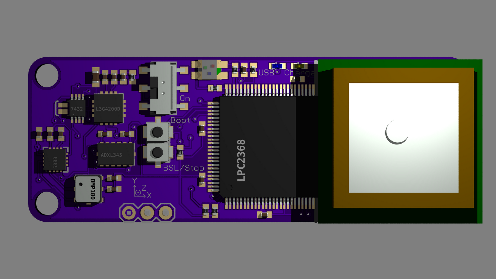
This one is designed from the ground up to be flight hardware. It has no reset button, its power switch swings perpendicular to the direction of flight, and the buttons will not by themselves stop the recording, like a reset button could. You can't see it under the GPS, but the micro-SD slot also ejects perpendicular to the direction of flight and is pulled back some distance from the edge of the board.
As if that weren't enough...

In a sense it doesn't matter since all those things don't have to be populated. Only the crystal, its caps, and the decoupling caps need to be placed. Everything else could come in from the edge of the board.
It still is a breakout, it's most prominent feature is a bank of 100 through holes for every pin on the chip. It is however forcibly mated to the 2368 and no other LQFP part, since the powers and grounds are connected.
I ordered parts for the Loginator2368, and will learn how to program it on that board. I hope I hope I hope that the USB design carried over from the 2148 will work, because that's what I have.
All these boards are marked Open Hardware, so if the designs fall into your hands, you are welcome to use and modify according to the Creative Commons BY-SA License. The Loginators and IMUinators have to be this way since they are Logomatic derived and Sparkfun made them by-sa. The breakout is that way by choice. I have not published the designs yet, as I am still working out the bugs. The designs will be published when they are ready, some time between now and... Ooh, shiny!
I guess I just like sending money to Laen and getting nice shiny purple boards. I hate populating them, just too much stress, although with the hot air rework, that is a lot less. I have more than one chance to get things right.
No comments:
Post a Comment