Project Precision has reached its successful conclusion. I now have a physical hardware clock with an hour, minute, second, and third hand, and enough accuracy to justify needing a third hand.
As I have mentioned before, I noticed that an Arduino Nano has precisely the pinouts necessary to drive a charlieplex with 240 lights. The interesting thing is how few leftover resources there are. There are two analog inputs that are useless in this design. Every single other pin is used. I even considered giving up the crystal inputs to get two more digital pins.I had to include a digital multiplexer since the ATMega only has one serial port, and it needs to listen to both the USB port and the GPS.
As I said before, I will not make one for you for less than $300. The parts alone cost almost that much. However, I am going to publish everything you need to make one yourself.
This is the Digikey part list:
Quantity
Digikey Part Number
Part
Value
Case
Placement
Price per
Min quantity
Ext Price
2
445-7483-1-ND
Capacitor
4.7uF
Ceramic 0603
C010 C418
$0.24000
1
$0.48
2
478-6025-1-ND
Capacitor
18pF 2% NP0
Ceramic 0603
C407 C408
$0.40000
1
$0.80
2
445-1316-1-ND
Capacitor
100nF
Ceramic 0603
C420 C502
$0.10000
1
$0.20
61
754-1359-1-ND
LED
Red 320mcd
LED 0603
D000-D059 D502
$0.14040
1
$8.56
60
754-1124-1-ND
LED
Yellow 150mcd
LED 0603
D100-D159
$0.11160
1
$6.70
60
350-2036-1-ND
LED
Green 300mcd
LED 0603
D200-D259
$0.51840
1
$31.10
61
350-2037-1-ND
LED
Blue 140mcd
LED 0603
D300-D359 D501
$0.48960
1
$29.87
4
CRA4S847CT-ND
Resistor Pack
47
CRA04
R1 R2 R3 R4
$0.04300
10
$0.43
2
P680GCT-ND
Resistor
680
SMD 0603
R501 R502
$0.10000
1
$0.20
1
CRA4S810KCT-ND
Resistor Pack
10k
CRA04
R606
$0.04300
10
$0.43
1
SW1021CT-ND
Switch
SPST
B3U-1100P
S429
$1.03000
1
$1.03
1
ATMEGA328P-15AZCT-ND
Microcontroller
ATMEGA328P
32-TQFP
U401
$6.45000
1
$6.45
1
768-1007-1-ND
USB interface
FT232RL
28-SSOP
U501
$4.50000
1
$4.50
1
NC7SZ157P6XCT-ND
Multiplexer
Noninv 2 input
SC-70-6
U602
$0.41000
1
$0.41
1
887-1319-1-ND
Crystal
16MHz
7M
Y401
$1.69000
1
$1.69
Lights
$76.23
Rest
$16.62
Total
$92.85
This costs on the order of $100, but the vast majority of the cost is in the 242 lights (240 for the hands, 2 for the TX/RX indicator). I get the above prices today from Digikey with no tax or shipping added on.You can get cheaper lights if you are satisfied with not using green or blue.
You will also need some connectors for the boards: Sparkfun Female Header Pack - a set of two 6-pin and two 8-pin sockets. You will need this complete set, plus another 6- or 8-pin that will be cut down to 4 pins. You might as well get two of these sets, since they are cheap Two Arduino 6-pin stackable headers
A strip of male straight headers and male right-angle headers. You need 32 pins' worth of straight headers and 4 of right-angle headers.
A long USB-A plug to USB-Anything cord. You are going to cut the cord off as far from the A end as possible.You will also need a way to connect this to the 4-pin right angle connector. I used a 5x2 ribbon connector (yes, 5, even though only 4 are needed. It's what I had on my bench at the time.).
While we are going through the Sparkfun shopping list, I recommend getting the UP-501 GPS receiver. In principle, any GPS receiver can work, and you can even set the clock over USB and have it run free without any GPS at all, but then you don't get sufficient precision to justify the third hand. The socket on the circuit board is designed for this UP501, and it fits nicely on the back of the board in between the four screws. If you use another GPS, you will need to make a connector for it. Get one that runs at 3.3V (or has a voltage adaptor) and one that has a PPS signal.
Finally, you need the light pipe parts. Ponoko does great work, but it is quite a bit more expensive than just the bare plastic sheets cost. The light pipes as I designed them are exceptionally fragile, and I forgot to put tabs on the light pipes to connect them directly to the four screws. If I were to make another clock, I would fix the latter flaw. As it is, the light pipes have holes for each LED, and these are used to hold the hands in place.
The firmware is plain ordinary Arduino code. There are two separate sketches, one to test each light in a controlled condition, and one to actually be a clock. The Charlieplex driver is put into a library so that the test code tests the same code that the clock code uses.
AppArmor is one of those things that our distribution engineers like to put into our Linux distributions without telling us. If you don't know about it, it can cause some WEIRD errors.
First off, AppArmor is basically another more restrictive set of file permissions, based not on the userid, but the filename of the process itself. If a process is not allowed access to a file by AppArmor, it will fail, just as if the permissions were set wrong.
If you don't know about this, it can be a head scratcher. Like for instance, I just moved my MySQL tables from their natural home to the raid. All the permissions are set properly, because mv does that when it can, and because I was root at the time. But MySQL still wouldn't work.
There is a set of file restrictions in /etc/apparmor.d/ . Find the right file, named after the process path but with dots instead of slashes (/etc/apparmor.d/.usr.bin.mysqld controls access by /usr/bin/mysqld). Set the permissions in there, and things will work.
So, as you may or may not know, I ran a nice little Linux server with all my data on it, including a filesystem dating back to at least 2003 with files back to 1999. I used LVM to spread the file system across all the drives I had, so that I didn't worry about which file was on which drive. I let the filesystem driver handle that.
Well, a couple of months ago, one of the drives in Omoikane started emitting this terrible shaking noise, which panicked the kernel. When I restarted the system, that drive was dead.
So, now I get to learn more than I cared to about the LVM and ext4 filesystems, in order to recover what I can from the good drive. As it happens to turn out, the system was in five "stripes", continuous blocks of LVM extents. Three of them, including the first one, are on the good disk, representing 2TB of the total 3.5TB system.
First thing is to write a really primitive LVM driver. I used the LVM tools to get a map of the stripes, then hard coded that map into my recovery program. This means that my program is not directly applicable to your problem, if you stumbled across this looking for LVM-saving hints. But, I did learn something about LVM: It uses the first 384 sectors (512 bytes each, 192kiB total) of each physical volume to record info about the entire LVM system the volume is participating in. This means that if any drive is still good, I can use it to reconstruct the structure, and find out which stripes I have and which I don't.
After the LVM header, each physical volume is just a trackless waste of unstructured bytes. The stripe information in the LVM header is needed just to see the order of the LVM extents on the physical volume. This is actually good, as it means that I don't have to interpret anything in the sea of data, at least in an LVM sense. To find the Nth extent of a logical volume, use the stripe map to get which extent of which stripe on which drive, then seek to 384*512+M*65536*512 to get to that extent, where M is the physical extent number you get from the stripe map.
Next it's on to writing a really primitive ext4 driver. Ext4 is rather sophisticated, in that it keeps track of a lot of data and uses complicated algorithms to decide where and when to write what. The good news is that Ext4 is a straightforward extension of Ext3, which again is an extension of Ext2, which was quite a bit simpler. Because it makes an effort at backward compatibility, much of Ext4 is readable with the simpler Ext2 logic.
For instance: Ext4 is divided up into block groups, same as Ext2. Each block group has an inode table and some bitmaps to help the full-blown driver allocate things quickly and optimally. Some block groups, always including the first, include a superblock with information about the entire file system, and a table of block group descriptors. Each block group table contains descriptors for all the block groups. So, in the first block group, we find a superblock, descriptors of all the block groups, and an inode table which lets us start finding files.
Now here's the clever bit. For a variety of reasons, pointers in different structures may point to blocks in other groups. That's ok, because all block pointers are absolute, meaning that they are all relative to the beginning of the filesystem. In one of the ext4 sophistications, it groups block groups into metagroups, and combines the inode tables and bitmaps from several block groups into one contiguous stream. For instance on Omoikane, 16 contiguous block groups made up a metagroup, so that the inodes for all 16 groups are in the first group. My code doesn't care, because the inode pointer in the block group descriptor points to the right place inside the inode metatable.
Another clever bit is in the directory structure. As is typical with a Unix filesystem, all the important information about a file is in the inode, including the file's length, permissions, owner, and block map. Everything you need to read a file, in other words. The directory only contains the name and an inode index. This is how hard linking is implemented: If two directory entries point to the same inode, then the file has two hard links, and each entry has equal claim to being the true name of the file. The directory entries don't even have to be in the same directory.
Ext2 just searched each directory entry linearly. Ext4 has the option of indexing the directory file, but it is done in such a way that Ext2 logic will completely ignore the index. The index data is actually in the directory entry for '..' after the file name.
In ext2, the closest thing to a "file allocation table" analogous to FAT filesystems is the block map. This map starts in the inode, which has the index for the first 12 blocks used by the file. Files of up to 48kiB are accomodated thusly. If the file takes more than 12 blocks, the 13th entry in the index points to another data block, the indirect block, which is completely full of pointers to the actual data blocks, allowing 4kiB*1ki blocks=4MiB more data, with the cost of 4kiB extra index data. For larger still files, we have the 14th entry which points to the double indirect block. Each pointer in this block points to another block full of pointers to the actual data blocks. 4kiB*1ki blocks*1ki blocks=4GiB more data, at the cost of 4MiB+4kiB more index data. Similarly the 15th entry points to the triple indirect block, which allows 4TiB more data at the cost of 4GiB+4MiB+4kiB of index data. Each step means about 0.1% overhead in storing a large file. Larger block sizes make the indirect blocks able to hold more pointers, so the level factor is more than 1024.
However, in ext4, a new block index called an extent tree (not the same as LVM extents) is used. The block map tree is fairly complicated, and needs to mark every block a file uses. Extents basically run-length compresses this by using one extent entry for each contiguous stream of blocks the file uses.
The above image is a 256x256 thumbnail from one of the front Hazcams on the Curiosity Rover, and represents more science data than sent back by any surface mission not sent by Americans.
And then there was this:
While recording the MSL entry data in canister mode, MRO also snapped this photo of MSL on its parachute. They said that this photo would be harder, because even though (or rather because) it's closer, the angular rates are higher. Well, this is a much better picture than that of Phoenix.
Go MSL! Stick the landing! Thousands of people have worked hard on you, millions are wishing you well.
Some humor:
When I say "overheard", I actually mean that I said that when I was working at a summer job at JPL. I'm not saying that I had any influence over arming the rover, but let's just say that all successful surface missions have been American.
I am throwing a zombified lobotomized Omoikane back into
the atomic banana peeler, just for its compute power. I have Unplugged
All the Things (drives) and am going to run it just off of a USB stick
with Ubuntu Precise on it.
I'm no Dan Maas. I don't have the time necessary to give this the attention it deserves. I don't have enough computer power to get a full model of both the lander and the terrain into view at once.
What I can do is easy. Spice kernels take all of the work out of predicting where things are. I don't need an aero model, I don't need a guidance program, I don't even need a numerical integrator.
So why do I bother? Especially in the face of this?
Because I like it. I love doing computer animations. I love collecting data and models. It's tradition started from Phoenix. If I had MER data I would probably do them too. And above all, Absurd Accuracy is Our Obsession. I have seen how SUFR works and how the balance masses deploy. They look weird, but a bit of though suggests its probably right. I have seen the lander scream into Gale Crater and descend against the backdrop of Mt Sharp. I have seen the parachute deploy and the backshell swing on it. I have seen the Skycrane Maneuver, and it doesn't look half as crazy as it once did. To be honest, its the part of powered descent before the skycrane that has me most worried.
Besides, it's not all bad. I finally found a nice map of Gale crater. So, my model of Mars lacks in detail, dozens or hundreds of meters resolution in topography, smaller but still large blocks in image map. Better is available, but not in color and difficult to mosaic. Besides, I don't have the memory for better. POV is particularly inefficient with meshes, and the maps I do have tax Aika's memory.
Anyway, with that map in place, with the backshell scorched, and so on, it looks good to me. Maybe I am comparable to Dan Maas. A little more time, a little more greeblies on the descent stage and rover (and perhaps Santa will bring me a copy of SolidWorks to do it with) and a little more patience and memory, and I might have a world-class animation. I at least hope to have a LASP-class animation to show on Sunday night.
...This time it is deploying various jettisonable objects. I could just Do It, but there is always a philosophy problem.
Jettisoning things is easy. We know the exact time and place ahead of time where each object will be jettisoned. It's easy to get an exact analytical solution ahead of time so that all we need is the time an object is jettisoned, and its position, velocity, and orientation at that time. There is an analytical solution to its future trajectory, and just apply some random spin to its orientation.
Except, I don't know that there really is an analytical solution when drag is significant. We can fake it with the entry balance masses, since drag is not a big part of their lives. But what about the heat shield? What about the backshell and parachute? What about the descent stage in its flyaway phase? We'll save that for last.
Apparently there is such an analytical solution, but only for drag proportional to the velocity, not the square of the velocity, which is the regime in which conventional drag coefficients work. There is another solution, but the horizontal and vertical velocities are implicit functions of each other. So, it's on to everyone's favorite brute force application! No, not a hammer, a numerical integrator. Almost the same thing though, I can see why there would be confusion.
Now the problem with numerical integration is that it requires a state. It requires memory. And due to the nature of the animation loop (I haven't restored persistent variables to Megapov yet, and it wouldn't do well in the Atomic Banana Peeler anyway) there is no convenient way to maintain this state. So, on each frame, we get to integrate all the way from the time of jettison to now. We can stop when we know the object in question is off-screen, so it will be for a few seconds at most.
Here's the current version of the animation, with the art for the descent stage and rover in place. Almost all the art is done now. I need some decorations on the backshell, to match reality and to show the capsule rolling (or not). Then I still want to char the backshell, and perhaps the heatshield too, as a function of integrated heat.
I have added a feature to my version of Megapov which allows access to a limited subset of JPL Spice directly from the Povray scene description language. Here is the sad part: It was written for Project Blinn, but Project Blinn was (may have been) lost in the Great Hard Drive Crash of 2012. So, I am going to use it on the MSL movie I am (still) working on.
Keil μVision 4 Debugger/Simulator. This is a small part of the larger (450MB, really guys?) μVision suite, but the only part I care about. With it I was able to debug my Task code, which is interesting given that I did not write or compile my code in μVision. Get the program and install it (it installs fine under Wine on Linux) and then bring up any example project, compile it, and get into debug mode. Then, right-click the disassembly window and select "Load Hex or Object File...". Now select the master .elf file that was compiled with GnuARM. It will load, and the simulated processor will be reset, so it starts at location 0 (of your code, apparently it skips the ISP).
I saw it! I owed it to Captain Cook to make my best effort to see the transit (insert 100+ years, 2117, etc) and I did.
OK, I didn't directly see it, but I did the next best thing, see it with a projection system. I had my binoculars pointed straight at the sun, then held up a white (so as to see it) box (so as to not blow around in the wind) as a screen. I used the shadow of the binocs to aim, and then used the focusing knob to, well, focus. I have previously seen sunspots with this setup, but it was too cloudy to really see them today.
Speaking of which, today is a partly cloudy day here at St Kwan's, and I was clouded out of seeing ingress. These images are from about 00:10 UTC 6 Jun 2012.
I have the old Logomatic 2.3 working with the new SDHC USB bootloader. At first, FAT32 was not enabled. because the mass storage part doesn't even need a filesystem driver, the host takes care of it. However, In order to find and install FW.SFE, the bootloader needs FAT32 however, so this version has it.
Also, the old Logomatic firmware has been updated the minimum amount to use SDHC and FAT32.
All of this works for me, and generates log files, but it sometimes takes a LONG time to mount over USB (sometimes a minute or more).
So here's the problem. There are in fact two SD card drivers in the Logomatic firmware. Hey, by the engineering method, anything that works is good, and the Logomatic code works, but it's not great code. There are entire sections that are included but not used, like the USB driver in the main logging firmware. Now we have two pieces of code to do the same thing -- access the SD card. There is Roland Riegel's code used by rootdir.c and used by both the bootloader and main code to read and write the card, and there is the code used by the USB driver, which is entirely separate and entirely unready to do SDHC.
So, I am going to update the USB driver to use Roland's code. This just means mapping what the code is doing now to the various parts of sd_raw.c . Piece of cake, probably. We'll see.
Anyway, once this is done, I'll post a message about it on the Sparkfun forums, direct them here, and get literally some readers on this blog, rather than just myself like I get now.
No bragging until I can put my code where my mouth is.
By the way: I am doing all of this development on the Loginator 1.1, so the SD card slot and USB port work. Yay for me!
It's sooooo close to being awesome. Cortex M3 with all the improvements (don't be scared by the word Harvard, the program-visible memory map is flat) and full pin compatibility with the 2368.
Almost.
This part has no SD/MMC port. Still, with SPI and DMA, maybe we don't need SD/MMC. The part is otherwise pin-compatible with the 2368, so the 2368 breakout board should work with a 1768 also.
I am going to get a 2368 talking to an SD card and sensor before I try messing around with the 1768.
I have every confidence that the board is correct. I have tested that the known bugs in the old board have been eradicated. I have every confidence that the parts are properly placed and that all joints are good. I have tested the power supply, charge circuit, and lights.
So why am I not more confident in this board?
Is it live...
...or is it Memorex?
All of the switches and the battery terminal were partially melted/burned with hot air. The power switch is especially bad. Everything seems to work, though. It's just ugly. Next time, we bake the plastic parts. Maybe we bake everything. Maybe we salvage this board by lifting all the burned parts, replacing them, and baking it. Maybe we just don't make this board again. I would kinda like to get out of the 2148 business and into the 2368 business.
Update: The thing is alive, the Arduino terminal just doesn't know how to talk to it. I sent ? and saw 'Synchronized' on the logic analyzer (great device, I'll write a review some day). It just didn't show up in the serial terminal. This means that the controller is alive enough to communicate over serial, which means that the crystal and decoupling caps are on and the power is properly hooked up. The thing was running on battery when I tested this, so the whole battery part works too. Wow, I guess a lot is tested just with "Synchronized".
I wish these pictures showed the glorious royal purple and gold of the boards.
This is a NON-FLIGHT configuration. Not that the Loginator is ever
intended to fly, anyway. This is just so that I can learn how to talk to
the sensors and get the IMUinator working
I finally put together an 11DoF. All sensors are on board, but I decided to forgo the OR gates until I see that I need them. That means that both solder bridges on the back are closed, and the board is subject to Analog silliness if it decides to show its head.
Here we have the design...
And here is the physical implementation. Is reality ever as clean as design?
All of these sensors work, in that the I2C compass and baro/temp sensor actually work, and the SPI accel and gyro respond to SPI commands and return their proper chip IDs. I haven't tested full functionality on those guys yet.
So, do I start making and selling these things for $50 each? Or do I just release the design and say "have at it" yourself?
Next version? There's always a next version. Both STMicro (makers of the L3G4200D) and Invensense (makers of the ITG3200 that I gave a glowing review to) have 6DoF sensors, and one of them even makes a 9DoF sensor with a magnetometer in the same chip as the accelerometer and gyro. The problem is that these parts are not yet available from Digikey, and therefore not really available at all. Also, the interfaces are ugly: Both parts have two SPI interfaces. The Invensense part has one for the gyro and one for the accelerometer, while the STMicro part has one for the gyro and one for the acc/compass. It is almost as if two devices are just crammed into the same case. I can cram together parts, in fact that's what the 11DoF board is. I want a 6/9DoF part to have a single SPI interface with a single chip select, and perhaps more importantly, I want the acc and gyro to sample at the same time and have one interrupt line.
I saw a new cool way to design a charlieplex, one which is easy and obvious, even for an extremely large LED matrix. This was buried in a post below where I blather on about my own problems, so I broke it out into a post that Google is more likely to find.
The boards for Precision 1.1 arrived on Saturday, part of an ocean of purple boards. I had previously ordered all the electronics for it, so I was all ready to assemble it, except...
In Eagle, I copied the crystal from some other source, and it was still labelled 12MHz like it was from some LPC2148 board. Before, I had manually ordered parts, but this time I used add-digikey.ulp, which dutifully noted that the part was 12MHz and the same case as the Logomatic crystals, so it ordered a 12MHz crystal and I missed it.
I had decided to use 91Ω resistors to try to solve the "extra lights" problem, but after having the clock set up, I decided that brightness was more important than extra lights, so I decided back to use 47Ω resistors like with Precision 1.0
This wasn't that much of a problem, as I had a complete but unusable board from a previous forgotten detail, so I could lift the 47Ω packs and 16MHz crystal from it, without ruining the working front board I already had. This avoids the "one brief shining moment" problem, when you have something that kinda works, but you want to improve it and destroy it in the process. I still have a working Precision 1.0 front board.
Now for today's $50 detail. The primary features of Precision 1.1 are the green wire fixes from last time and a port for the UP501 GPS unit in place of the EM406 port from 1.0. Well, I was planning on using the back board from Precision 1.0 as-is, since it already has $50 of blue and green lights on it. However, it has the old GPS port on it, with certain pins grounded and certain pins connected to VCC - the wrong pins, as it turns out. One of the new 3.3V pins matches one of the old VCC pins, so there is a direct 1.7V short, which I'm surprised didn't completely burn out the FT232. Maybe it did partially burn it out, but there is no way to check right now. The new PPS pin is grounded on the old board, in a flood of polygon that is impossible to isolate. Even though the back board has no electronics on it, it still interferes. This is the $50 detail. Now I have to order a new set of lights. Or... I can lift the lights off of the old board, but that would create a brief shining moment problem. So, it will be new lights.
I just got finished reading Digital Apollo, where one of the major themes is how much automation is the right amount. The author refer to the two poles as "Chauffeur", someone who just wants to get a job done, and "Airman" (I will say "pilot" from here on out) who flies for the joy of flying and personally controls a complicated machine. This debate can be easily seen in other machines, as well. For instance, do you like a manual or automatic transmission?
Are you worthy of the term "driver" if your idea of driving is getting on I-80, turning on cruise control, and doing only what is necessary to stay on the road and not hit anyone? Would you like to turn those tasks over to your car as well?
On the other hand, do you love choosing the exact shift points to get the most out of your car? Do you want to be able to do things in a manual that you just can't do in an auto, like a push start or engine braking? Why don't you use a manual choke as well as a manual transmission? Is there a manual timing adjust in your car? Fuel injector control? Theoretically, a manual transmission can be more efficient than an auto, but is it really more efficient in your hands?
I for one am squarely in the automation camp. I drive because I want to get somewhere. I program for the fun of it, the way that some people drive for the fun of it. After being around and fascinated by the aerospace business over my whole life, I finally discovered that I am not a pilot. I like the idea of space travel, and I wish I could do it, but I'm not one who likes to control my machines that much.
Digital Apollo is mostly about the struggle between the computer and software engineers, who just wanted to get the job done, and the astronauts who wanted to actually fly in space, rather than just ride. In the late 50's and early 60's, it was becoming increasingly difficult to justify human controllers. For instance, no US rocket has ever been manually flown from the ground into orbit. Ascent guidance was developed for ballistic missiles which obviously couldn't carry a pilot, and this guidance was adapted to launch vehicles targeting orbit instead of targeting flaming death on our enemies.
Even if a human was to control a rocket, they would not be able to navigate or guide it. Navigation is done by the inertial measurement unit (IMU) and some software to integrate its measurements. Guidance is done by some complicated formulas which take the current and target state vector as inputs and produce a vector to align the thrust to. All that a human would be able to do is point the rocket in the direction that the automatic system already calculated.
All this brings us to the most complicated maneuver ever attempted in space, deorbit and landing on an airless world at a particular target in a safe spot. Surveyor performed landings, but had an error ellipse on the order of tens of miles, and it landed directly from an impact orbit. Apollo was a complicated coordination of humans and machines, each doing what they were best at. The program was broken up into several major modes:
P63 was called Braking, and lasted from before powered descent initiation (PDI) to the "high gate", where the landing site came into view. P63 was basically full automatic, where the only job of the astronauts was monitoring. Its job was to get from orbital speed, about 1.8km/s, at about 16km altitude, to almost stopped, only 200m/s or so at 3km altitude, in the most fuel-efficient way possible, and without hitting the ground. Calculus of Variations provides a unique trajectory, which the guidance system attempted to follow. It carried an approximation of this trajectory, perhaps similar to the powered explicit guidance routine. Early in the descent, the surface of the moon was too far out of range for the landing radar, so the guidance source was the inertial platform. After descending lower, the radar became active and the Kalman filter navigation system used the radar and inertial observations to produce its estimate. The guidance equations took the Kalman filter output as its estimate of where the vehicle is, and calculated the correct descent engine pointing to fly the best approximation of the optimum trajectory from the current location to the high gate.
P64 was the visual approach. At this point, the lander tipped over so that the commander could see the landing site through the windows. Before this point, the vehicle was pointed almost level, with the standing astronauts' feet towards the direction of travel and faces straight up into space. P64 was targeted to a low gate point, and flew the best trajectory it could, with the constraint that the commander could see it through the window. It also calculated where it would land if allowed to land automatically, calculated where in the window that would be, and displayed the Landing Point Designator (LPD) angle, which the lunar module pilot read aloud. The commander would use the angle scale engraved on the windows to see where the vehicle thought it was going to land, and could change this point with the rotational controller. If the commander did so, the program would recalculate the location of the low gate, so that guidance would fly to the new point instead of the old. This is an example of cooperation between manual and automatic processes. The commander used his senses, particularly vision, to evaluate the landing site. The machine can't see at all, it is basically a blind machine with a radar as a white cane. The human chooses and evaluates a landing site, and the machine figures out the best way to get there.
P65 was the automatic landing program. After passing low gate, the program nulled the horizontal speed and followed an altitude versus vertical speed profile to land. At this point, there was no targeting involved. The program was committed to the last LPD in P64, and just used the radar to measure altitude and run the vertical speed profile, and to measure horizontal speed to null it. No mission was ever landed with P65. During P64, the commander always switched to...
P66, altitude rate control. In this mode, the commander chose a descent rate, and changed it by clicking a switch up or down. He also chose the attitude by using the rotational controller. The machine calculated whatever thrust was necessary to hit the commanded descent rate, controlled the descent engine throttle, and calculated but did not control horizontal velocity. It displayed that on the cross pointers on the commander's instrument panel, and left it up to the commander to control horizontal rate. This is almost always referred to as the commander taking manual control, but as we can see, again there is a strong automatic assist, the machine doing the calculating, the human doing the guidance. Horizontal speed and position was controlled similar to a helicopter, by pitching the correct direction to use some of your thrust to add or subtract to your horizontal speed. It was up to the commander to make sure that by the time the vehicle was on the ground, its vertical speed was slow enough and its horizontal speed was close to zero. All Apollo missions were landed with P66. There was also...
P67, Full manual. The machine used the radar to calculate altitude, vertical and horizontal speed, and so forth, but only to display them. The commander had full control of the throttle and attitude. This mode was never used.
Actual attitude control, even in the semi-manual and full manual modes, was provided by the digital autopilot, in what we would now call fly-by-wire. This program figured out which RCS jets to fire, based on inputs. The autopilot itself could be driven by the guidance system, which calculated the best way to get to a chosen attitude (KALCMANU routine) and drove the jets that way. It could go on semi-automatic Rate Command, where when the commander moved the rotational controller, the machine would figure out the axis the commander wanted, then use the jets to get the vehicle rotating around that axis at a given rate. As the commander held the rotational controller, the vehicle would continue to rotate, with the jets quiet, since the vehicle is now up to speed. When the commander released the controller back to center, the digital autopilot would stop the vehicle rotation. There was also an almost full manual mode, where the jets were on as long as the controller was moved. This is most similar to the native Orbiter mode.
Similarly, the Space Shuttle guidance system could do deorbit braking, entry, descent, and landing all the way to touchdown, all on automatic. The only thing it couldn't do automatically was lower the landing gear. This was for safety so that the gear was not lowered in space, since they could not be raised once lowered.
The shuttle was flown in autopilot through 134 of 135 entries, but 0 of 135 landings. The commander and pilot always flew the final approach, from near or in the HAC to touchdown.
The automatic entries are a little bit surprising, as in Orbiter, I like to fly space shuttle entries on almost full manual, and I don't even like to fly. Skidding across the atmosphere at mach 25, 40deg nose up and 80deg banked, may be some of the most fun and exciting flight possible. I use the Glideslope MFD to see the reentry corridor, but stay on it myself. I'm not just flying to pre-calculated needles either, like I would in an ascent. I am actually doing what pilots do - flying by the seat of my pants.
There was a proposal to do a fully automatic unmanned landing of the lunar module, but among other things the astronauts hated it. I think the same thing happened with the shuttle. If the full auto system is proven, then why do we need pilots?
Automation is your friend, not your master. Besides, if you are the one building the automation, then it is the friend you built. I have heard it said that you can program a computer to dance and Irish jig, but only if you know how to dance an Irish jig. I would add further that while you have to know how to do it, you don't have to be able to do it yourself.
If you are buying your own car or plane, for the fun of driving or flying it, be my guest and have it however manual or automatic you want. If you are flying for me, whether I am a passenger on the aircraft with you or just a taxpayer paying for your ride, you are obligated to do whatever will maximize the chance of mission success. If that's full manual, so be it. If full auto, so be it. Some combination? Choose the right combination. Don't be like some astronauts who thought that they were destined to fly a lunar module and wanted as little automation as possible, to prove how macho they were as pilots. You are there in support of me, the science-consuming public. We did not spend billions of dollars so that you could fly. We spent it so that we would get the mission results.
By the time you finish one invention, you're preoccupied with your next.
--Dee Dee to her brother Dexter
That's me. I haven't finished the old Loginator, even though I respun the board. I am now fascinated by the LPC2368 as described below. The Loginator2368 is my increasingly less compatible Logomatic clone/extension. This one has the same form factor as the Logomatic, and same 20 pins on the one edge, but the similarity ends there. The LPC2368 is vastly superior at recording digital events, and vastly inferior at recording analog ones. It also has six PWM outputs and a port for the 11DoF, so it is a good candidate for a robot brain, if I were interested in making those any more.
A couple of days ago, I formally cancelled my plans to compete in this year's AVC. I was on backorder, and hadn't even started my robot yet.
So, I guess I can spill my secret plan now. If anyone wants to run with it, fine. I don't even need credit.
I was going to build a biped. The design is based on the little wind-up ducks you can get that waddle along on two feet. The feet are designed such that the device is stable without active balancing.
My idea was to use a four-bar parallelogram linkage, with two stepper motors to make sure they always turned in sync. A third motor was at the knee of one of the legs, to do steering.
It is not designed for speed, but for coolness. I didn't want to do another robot built into an RC car. That has been done to death, and I couldn't do it last time anyway.
I have a new favorite microcontroller: the LPC2368. It programs similar to the LPC2148 but is much more "digital" and much less "analog". It has four UARTs, three SPI ports, three I2C ports, something called I2S, two CAN ports (maybe I can talk to my car, or more like listen to it), two USBs, an ethernet port(!) and so on and so on. One big deal is a hardware SD/MMC port. My previous new love was the 2468, but that one has 208 pins and probably wouldn't fit on the Logomatic footprint, much less the stick IMUinator.
This guy has exactly 100 pins. The one big feature that the 2368 lacks is an external memory interface. That and a lot more GPIO pins. For two main reasons, the 2368 is more convenient to work with than the 2148:
More pins means less overlap between functions. Several of the peripherals have dedicated pins (Ethernet, one I2C) so there is no problem with overlap. PWM and UART still overlap, but there are enough pins and two choices for each overlap that you can use all 6 PWMs and all of the UARTS.
Fewer analog inputs, so those don't take as many pins.
The last is the only place where a 2148 is superior. The '2368 has six A/D inputs, but I use one of them for battery voltage, one for current, one for reference, and one is covered up by the USB Vbus input, leaving only two for use. You can sacrifice the voltage reference to get another channel, and I should think about doing the same for battery level and current sensing. It may also be possible to use another plain GPIO pin as Vbus, freeing up another A/D.
All the sensors I plan on using now and in the future are digital anyway, so to me, losing A/D is no big loss.
Also, all the peripherals except I2C have DMA, which I think means you can hand them a big block of data (or tell them to listen for a big block of data) and then the peripheral will take care of itself, while the core continues its programs. No more busy waits for the SD card.
I am working on a Loginator2368 which is increasingly less pin-compatible with the Loginator, but still roughly the same shape and size. Who knows if it can be made to fit on a Stick IMUinator?
I lifted, or burned up and buried in burnt rosin is more like, one of the pads that I needed to connect one of the short green wires to, across U601, so that the USB could listen to the ATmega. Double drat. I NEED that connection.
Well, I start doing an inventory in my mind... I have an extra copy of this board, enough of almost all the parts I need, and a hot air rework to pull parts off of the old board. I have everything I need to build a new copy of the top board (with all the logic on it, not the LEDs yet). The only thing I lack is another FT232, and that is easy enough to get from Sparkfun. I don't buy them out this time (and they restocked their ATmega's the same day).
A little of this, a smidgen of that, find the old parts template, and boom. No, it didn't explode, it in fact worked after I changed the software to use the right lines.
Here's what I have learned so far about surface mount soldering:
It is possible! Really, you can do it.
It's harder than it looks.
My process is as follows. First, design the board, send the .brd file to Laen and send a gerber of the cream layer to Pololu. Yes, you want a stencil. Yes, even for one board. Also make sure you have all the electronics you are going to use.
After the parts arrive, including the components you are going to place, gather everything up. I like to make two sets of paper documents. One is a placement sheet, showing where each component goes. I make Eagle make me an .svg file, then suck it into Inkscape. A bit of cleanup, then highlight all of one kind of component, say all the 100nF 0402 capacitors. Then, make a copy of the drawing, lowlight the highlighted parts from the previous step, then highlight the parts from the next step. There were 24 steps on the Loginator, and each part went from gray to white to black in turn, until all the parts were black.
The other one I do by hand with a pencil. I draw a grid on a clean sheet paper, with the same number of cells as there are steps above. I then get the right number of each component from my stores, and put them in the right square for the step.
For stores, I have one of those plastic boxes with lots of little drawers. It has 6 columns and 10 rows, for a total of 60. Each drawer has a divider, so I could store up to 120 different kinds of parts. I number the drawers from 0 to 59, and label the front half A and the back half B. I have a spreadsheet inventory, but it is gradually going out of sync, mostly as I use parts.
Anyway, I number the boxes, and write the value, package, schematic part number, and drawer, in the corners of each box. The drawer is so that I know where to get another 0402 capacitor after one springs out of my tweezers on a magical voyage through space and time, never to be seen again.
After all the parts are out, it is time to stencil. Pololu stencils come as an 8.5x11 sheet of plastic. DO NOT cut the stencil! Big is OK. I made a mistake and cut the middle part out of the Precision stencil. Small sheets of plastic tend to curl and lift off the board, making things hard to work with.
Now, a tip from the guys at Sparkfun. Tape a couple of old circuit boards to your bench, such that your new board is framed and immobilized. Two is usually enough for a rectangle, but for the circular board for Precision, I used three rectangles. Now CAREFULLY lay your non-cut stencil on the board. I'm right handed, so I securely hold the stencil down with my left hand. Even with a transparent plastic stencil, it is easy to see when the stencil is perfectly lined up. Make sure that the stencil is lined up with the pads on diagonally opposite corners simultaneously. Also make sure that you are looking straight down on the stencil. Stand up if you have to.
I use a square-nose X-acto blade as my squeegee. It's about half an inch wide. I get my soldering paste in a syringe, but had no luck with the tips, so I just uncork the syringe and squeeze some out on one end of the stencil. Careful here, solder paste is so viscous that it keeps coming out for a little while after you stop squeezing it. Now I use the X-acto blade to spread the paste out. Press hard enough that most of the paste is carried along, and the stencil is mostly clean and transparent after the blade passes. Make sure that all the holes are filled. Sometimes they are easy to miss, and sometimes they are so big that one pass doesn't fill the holes. Don't be afraid to make multiple passes.
Now use your right hand to pull the stencil tight. This will lift it straight up off the board. Lift with your right hand until you are sure you are well clear of the board. Only then can you move your left hand. If everything went well, you should have a nice little square box of solder paste sitting on top of each pad. If not so well, use some rubbing alcohol to clean the board and do it again. The solder paste doesn't have to be exactly in the middle of each pad, but it isn't good to have a bridge either.
Now, use some sharp tweezers to place each part. For me, especially on the small 0402 parts, they invariably end up sticking to the tweezers, and I use this to my advantage. I can pick up a part, then let the tweezer tips separate. The part will stick to one and not fall off, so I use just that tip. I place the part all the way down, so that the solder paste sticks more to the part and pulls it off my tweezers.
For larger parts, I usually drop them from about 1mm up, then gently nudge the part as needed for accuracy. Precision counts! Align things up as well as you can, to avoid bridges.
Once all the parts are placed, it's time to bake. I am using a convection toaster oven which can get to 230°C (425°F) without turning on the broiler. That isn't really as hot as I wanted, but the EP256 solder paste I have has a peak of 210-225°C, so it's probably alright. I got convection because I really want to do the soldering with hot air, not direct radiation. Hot air will get heat sinks as hot as the boards, maybe hotter.
This is the exact procedure I use. Once a board is stuffed, it is put on top of the small cookie sheet that came with the oven. I put the rack in the middle, and put the board as close to the convection fan as I can. The temperature dial is set at 450°F and the timer is set to "Stay on" which turns the oven on. So, I watch for the solder to melt, which is a very visible and sharp change from dull gray to quicksilver. I then count to 20, then open the door and turn the oven off. This consistently takes 5 minutes 20 seconds.
Now it's off to the microscope to check all the connections visually. This isn't conclusive, it finds bridges but not disconnects. So, I use the schematic and board layout to check continuity between each of the 32 ATmega pins and where they are supposed to be going. All the charlieplex pins should have 47 ohms from the ATmega to the Q signals, since they are going through one current limiting resistors.
Now for the green wires. One from D11 to P01, to the corner of one of the resistor packs. That is a very small target to solder, so I have to use the stiffness of the wire to hold it in the right spot (basically use the wire itself as the third hand to hold it). D13 goes to P16, also a corner. On this second copy, the 10k resistor pack didn't solder on one whole side, and I lifted the whole component (but not any pads) trying to fix it, so I put in PTH resistors between the through-holes on the side. Now that I think about it, it is good that part did lift, since D11 and D13 were being pulled up by those resistors. Only reset and D12 need to be pulled up now.
Do the same Arduino bootloader as last time. Oh drat, the red light doesn't blink. Not worth fixing, I probably got that one backwards.
I got the green wire soldered to the corner resistor P01... once. It was looking awful fragile and hanging-by-a-thread-like, so I smothered it with hot glue to hold it in place. Guess what... So, now I have two 100Ohm resistors twisted together to approximate 47 ohms, soldered directly from D11 to Q01. P16 is still hanging on, under it's blob of glue. It's ugly, and definitely does not have the Ipod-like polish I am looking for, but it works, and confirms that the next spin of the board will work.
Once the software is ready to use the new pins, the charlieplex works! I think that these 17 60 lights excercise all of the signals, so everything is great! The little out-of-turn pulses I think will go away as I install more lights and complete the Charlieplex.
Lights 4 and 5 on the back of the second board (where I am installing the blue lights) won't light. As it happens, neither will any of 54-59, but we'll save that part of the story for later.
I remember the solder bridge between two pins, and one of those pins, A7, is involved with the lights that don't work. So, we carefully measure pin A7 and conclude that no matter how we program it, it acts like a high impedance. The natural conclusion is that it is burned out. So, run to Sparkfun, buy their last three ATmega328s, and a hot air rework station to pull the old chip. Carefully remove the old chip, taking care not to scorch the white paint on the board or blow away any of the passive components. When the chip comes off, it comes off great. Put in a new chip, verrrry carefully check continuity between each pin to make sure there are no bridges or missed joints. Fix a couple of missed joints. Guess what. The board acts exactly as it did.
So, that theory is shot. I might have burned out pins on this chip, but exactly the same pins? I think not. Now time to gather more evidence for another theory. Write up a program that listens for commands on the serial port and turns individual signals high or low, with the rest at high-Z. Signals 1 and 16 are both no good. What is going on?
The Arduino documentation says that you can use the analog input pins A0... as normal digital pins with the syntax pinMode(A0,OUTPUT); digitalWrite(A0,HI); etc. Which is in fact true, but only to a point. On an ATmega328, pins A6 and A7 are internally called ADC6 and ADC7, not PB...(ADC6) or anything like that. They are dedicated input pins. I had been planning (as in had a circut board made) to use A6 and A7 as Charlieplex lines 1 and 16. Guess which Charlieplex lines don't work... And guess which signals lights 4 and 5 (and 54-59) use...
I have no one to blame for this but myself. It was right on the Eagle schematic symbol the whole time that all the other A0... pins were secondary uses of GPIO pins, but A6 and A7 were only labeled as ADC. I guess the weird part is that the crystal inputs and reset line are alternate uses of GPIO lines, but A6 and A7 are not.
So, here's the plan. Lots of green wires, hot air, and razor blades, to hack D11 and D12 into P1 and P16. This will require giving up two multiplexers, which completely hashes my plan to use the GPS. At least this will let me test the charlieplex. Then, order 16 more blue lights, another FT232 and a correctly wired board which uses the crystal pins as two more digital outputs, allowing me to use D11 and D12 as multiplexer controllers on the next rev. NO getting a new board until all the green wires are fixed. Don't even touch Eagle until the last green wire is in place and CharlieTest works. Consider putting a LiPo battery power supply on the next board as well.
The moral of the story is keep working the problem until you find the problem, and don't guess. I have a nice new hot air rework station which works really well, and costs more than the LEDs combined. Oh well.
I finally invent something that works!
-- Dr Emmett Brown
Well, I have just built an honest to goodness Arduino, a round one connected to the most elaborate Charlieplex I have ever heard of... but no light on D13, so I can't even test it with the Hello World for microcontrollers, blinking a light. So, I used the ASCIITable example, to see if I can get code on the machine and have it run.
I made (at least) one mistake in the board design, and had to run what may be the shortest green wire ever. The FT232 datasheet clearly states that the TEST pin must be grounded, or the device will go into test mode and not show up on USB as expected. Well, I didn't ground TEST on the circuit board, and the device didn't work as expected. However, there is one bit of good news. The pin right next to it is ground. So, one bridge removed from the ATmega, and one added to the FT232, and we are ready to go.
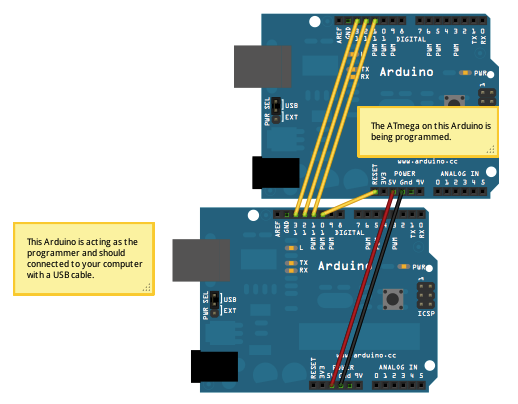
First, load the ArduinoISP onto the Nano 3.0 I have.
Next, connect it to Project Precision, while the Nano is unplugged.
Neither of the Arduinos involved look like this
I cleverly broke out the six pins needed to do this on Precision, so it just needs a ribbon cable from a breadboard to the connector on Precision. I used individual jumper wires to connect the pins on the Nano by label to the correct wire in the ribbon cable.
Next, plug everything in. First carefully check that the ribbon is plugged in right, then plug the Nano into USB.
Now run the bootloader instructions. All four lights on the Nano will light up simultaneously (something I hadn't seen before) and blink like crazy (except the blue power light).
Board the device and bring it to life!
Finally, pull the plug on the Nano and plug in Precision. I thought about writing a literal "Hello World" program, but it was just easier to run the ASCIITable sketch.
One of the things I used to have to do with all my custom boards is take them into the lab at work. There they have a really nice optical microscope. This one looks at things instead of through things, so it is appropriate for electronics (funny that, being in an electronics lab). It doesn't have an eyepiece as much as it has a facepiece. The end you look through has a screen (pure optical, no electronics or cameras involved) about 5 inches wide. It gives you a stereo view with a single objective lens, because each of your eyes is looking through a different optical path in the same set of lenses.
I have been searching for something like that and finally restricted myself to something I could actually afford, a USB digital microscope. I ended up getting this microscope.
Here's what I got it for - finding solder bridges
Really short depth of field. Do you want the top of the chip in focus...
...or its leads?
The subject of this particular set of pictures is Project Precision. For about five years now I have had a design in the back of my mind for a digital handed clock with an hour hand, minute hand, second hand and third hand (1 third = 1/60 second. Yes, really. Isaac Newton used thirds in the Principia.). I had a design using all 7400 series logic, a PIC and less 7400 logic, but finally came across the concept of charlieplexing. With 16 pins, I can control 240 LEDs. Only one at a time can be on, but I only need four on at a time, so I can strobe through those quickly enough.
The thing is USB powered with no battery. It uses an ATmega328 as the core and an FT232 for USB-UART conversion. This basically makes it an Arduino. It has a port for a GPS receiver as well, and a couple of multiplexers to connect the ATmega, FT232, and GPS in any combination.
What I'm most proud of is the layering. I needed 60 LEDs for each hand, and with four hands, I needed the front and back of two boards. I figured out a way to make these boards identical, so when I got three copies, I had enough, and didn't have to order three copies of two different boards.
Charlieplexing involves pairs of LEDs, pointing in opposite directions. If you set one end of this combo to VCC and the other to ground, one of the pair will light. If you do it the other way, the other will light. What I have done is put half of each pair on one board, and the other half on the other board. All the LEDs on the board with the logic will point outward, while the LEDs on the other board will point inward. It's almost fate that 16 signals can control 240 LEDs, the exact number needed for four hands. 16 was the exact number of signals left on the ATmega after I accounted for the UART, clock, multiplexer controllers, etc.
Now for the tedious task of picking and placing 240 diodes... Fortunately I only have to do them 60 at a time.
No, I will not make one for you, not for any price. Well maybe, but it would have to be a lot. Better is to make one yourself.
All purely computing parts of the Loginator have now been tested. The power supply, USB, SD card slot, RGB light, and BOOT button all work. The charger circuit itself works, but I installed the LED backwards.
None of the analog parts have been tested. The current sensor was originally too hot to touch when the board was on. I tried to remove it, but in the process of hitting it with the soldering iron I must have fixed it, either that or it is burned out completely. Won't know until I test the analog part. I also realized that I should have gotten the 100V/V part instead of the 20V/V part. This is fixable without any board modification.
I may have made a foolish decision in relation to the RGB light: you can't run the lights as lights at the same time as you use the UART ports. Honestly it's not my fault. There are six PWM pins, but four of them are shared with TX and RX on the two UART ports, one is shared with the chip select pin for the card reader, and one is AD6. Right now I just use the blue and green lights, which overlap UART0. The red one overlaps TX on UART1.
I put into the Logomatic main firmware code some compiler switches so that it can be switched to be Loginator with one switch. This controls where the code looks for the lights and STOP button. With this switch set, the Sparkfun firmware now runs on the Loginator. It is even bug compatible - the first log file is LOF01.TXT. Next is to get Logomatic Kwan adapted the same way.
The SPI port with the SD card on it works, but I haven't tested the other SPI port or either of the I2C ports. I made a silly mistake and wired a pullup resistor to SCK1 (SPI) instead of SCL1 (I2C). I2C0 is fine, but the 11dof port uses SPI1 and I2C1, both of the affected busses. This is fixable with a green wire and a cut trace. The board modification does not require a new stencil.
I jumped in face first with the SDHC patch and got burned. The Logomatic code now no longer creates log files. I have seen through the serial port that the code is reading the configuration file, but cannot or will not write the log file. What I will do is back out the FAT32 part and just use the new SDHC part, to start with. Once the Logomatic with SDHC works, I will update the bootloader similarly, then actually try it with an SDHC card.
I have been looking at the LPC2468 chip. It has a purpose built SD port, DMA everywhere, USB, Ethernet if I ever wanted to use that, lots of cool new features. It's even cheaper than the LPC2148. The only problem is that it is a 208 pin chip, and I don't know if I will ever be able to solder down such a chip. Also its 28x28mm, so it may not even fit in the Logomatic board footprint. DMA is cool because it is like an arbitrary-length FIFO for every device, anywhere in memory I want it.
I mentioned below that I had developed a method of attaching all the source code to the firmware and then having that very firmware dump itself to its log. The problem is that it takes a long long time to do this. Partly this is due to the one per second packet dump rate, and partly because hexadecimal coding doubles the data size and adding packet headers adds yet more data.
So, here's what we do. For binary packets, we just do it. Dump 64 bytes at a time into a header with 8 bytes of overhead.
For NMEA packets, we do something smart. We use Base85 encoding. This is a method of encoding 4 bytes of arbitrary binary data with no restrictions, into 5 characters carefully chosen to all be printable. Base 85 is the smallest base where 5 symbols can be used to encode the 4Gi combinations possible from 4 bytes. There are 94 printable characters, so base85 will work. Base84 won't encode 4 bytes, and Base86 doesn't gain anything.
Postscript standard Ascii85 has a couple of cool features but also a couple of drawbacks. They just use the number calculated plus 33, so as to use characters from "!" to "u". If four consecutive zero characters are transmitted, these are compressed to a single "z". If four consecutive spaces are transmitted, this goes as a "y". There are several more characters that can be used, but one of the drawbacks are that "," and "*" are used. Comma is not a killer, but star is, since it marks the end of the packet.
Since there are 94 printable characters, we can decline to use certain characters like comma and star, to fit the NMEA structure. So, one thing to do is to switch out star, and might as well do comma as well. Star turns to "v" and comma turns to "w".
The compression mentioned above is nice, but since the LPC uses NAND flash, "empty" areas are actually filled with 0xFF, not 0x00. So, we will steal "x" for encoding 4 consecutive 0xff.
Another alternative is to just make an array of 85 characters in any order that we want. We have already given up Postscript compatibility, so why be constrained by it? The Wikipedia article mentioned above mentions RFC1924, which uses 0-9, A-Z, a-z and !#$%&()*+-;<=>?@^_`{|}~ in that order. It refrains from using ("',./:[]\) since those are harder to escape. We could choose one of those in place of star, and several other for compression.
Your Logomatic probably doesn't need fat32. It probably doesn't need more than 2GiB files or 2GiB of storage total. It probably doesn't have the battery life to support writing 2GiB.
But microSD cards that aren't SDHC are becoming hard to find. The hardware needed to interface SDHC is no different than normal microSD. It's just software. Your Logomatic (or mine for that matter, constructed in 2009) just needs a mind transplant, a simple firmware upgrade. Well, not so simple, because that firmware doesn't exist yet.
That's where I come in. I am back in the Logomatic (and Loginator, which is substantially the same) business, for the while until my attention drifts elsewhere. Hope I finish, or hope that you or someone reading can pick up where I leave off.
Remember that both of these programs are installed at the factory on each Logomatic, so you already have these in compiled form. They share no memory, but have much identical code. See, the USB bootloader needs to access the SD card, both to do the USB mass storage thing, and to check if your firmware FW.SFE file is there and read it and install it if necessary. It also has a USB driver to convert USB signals into microSD commands and vice versa. The Logomatic main firmware needs much of the same code (except for the USB part) to read its configuration files and write data to the card.
This code comes in the form of some .c files, along with supporting .h files. These files were the work of Roland Riegel, and through the magic of open source, we get to read and modify them as we see fit. As it turns out, Roland has already modified his code to handle SDHC cards, and as a logical extension, the fat32 file system. So what is left to us? Modifying this code to handle the LPC2148 chip instead of the ATmega32 that he uses. Yes, I just saw you Arduino users' ears perk up. Sorry to dissapoint, but I am not going to do anything with either Arduino or ATmega, but that doesn't mean that you can't.
So, here is how the sd-reader (as Roland calls his whole work) is structured. At its lowest level is sd_raw.c . This file is used to control the card and read and write blocks of it. This code can be used directly if you want to use the sd card without worrying about unnecessary bloatware like file systems. It also is used by the USB mass memory driver. In this case, the USB host (probably your desktop computer) sees the USB device (the Logomatic and its SD card) as a featureless sea of blocks. The USB wire protocol just concerns itself with reading and writing those blocks, along with such bookkeeping things as determining how many blocks there are. The USB driver in the LPC2148 mostly just interprets USB commands and uses the sd_raw library to fulfill these commands. The LPC2148 in this case doesn't care about filesystems. The host sees the raw blocks and it interprets them as a filesystem. In principle, this allows the host to use any filesystem it wants, without the Logomatic caring. If you wanted to, you could format the card in a Logomatic as fat16, fat32, ext4, whatever Mac uses this week, etc. We will see why this is not a good idea later.
On top of this low-level interface, we have
fat16.c, which knows about directories and files
rootdir.c which sits on top of fat16 and makes it so that your code doesn't have to worry about directories
partition.c which reads the partition table on the sd card and finds the partitions so that fat16 knows where to start.
The file reader in the USB bootloader and the file reader and writer in the Logomatic main firmware are both based upon this code. This code specifically assumes that the card is formatted as FAT, FAT16 to be specific. If your card is not formatted as FAT16, then the USB bootloader will not be able to find and load FW.SFE. In this case, the code is running free, without the guidance of the USB host to interpret things. It needs to interpret the data on the card as a filesystem all by itself. If the filesystem is not FAT16, fat16.c will detect and complain about this, and the files will not be read nor written.
So how are we going to use all this code which was written for an ATmega on an LPC? That's the magic of C code and compilers. 99+% of the C code in these files will compile without change. This includes all of fat16, rootdir, and partition. These use sd_raw. Sd_raw in turn is about 99% portable as well. It knows the SD wire protocol, and how it sits on top o the SPI protocol. All it needs to know about the hardware is what registers control the SPI protocol and how to use them. This knowledge is isolated into a couple of functions, and we need only change these functions to port the code from ATmega to LPC. Almost all this code is already well-isolated, there is just one bit left that can be broken out.
The Sparkfun Air Show has been cancelled. No helicopters or quadrotors allowed. It just didn't seem like a good idea to them to have an autonomous spinning blade of death out on a course surrounded by hundreds of spectators. I support their decision, but it certainly puts a damper on my enthusiasm to build Arisa.
I didn't buy an entry in time. I have an entry in now in backorder, but who knows if or when that will come in.
I was too ambitious last year. When the helicopter burned out, I only had a week to try to build a car, and didn't get it done. This year, the plan is:
Get Yukari working, which means getting the Loginator working and repairing/replacing the steering servo in the car. Yukari is done when it can drive around the school.
Build the Secret Project. I have an idea for a robot unlike any other seen at any previous AVC. Information wants to be free, especially secret information. You only own an idea as long as you don't share it (there is no such thing as intellectual property, a subject for another post) so the Secret Project will remain secret. Even the name is secret. As if from Paranoia, the classification level of the document is also classified. This is partly because a) if you knew the name, it would reveal the design, and b) I haven't even given it a name yet.